Search
Italiano
English
Español
Français
العربية
Русский
Português
हिन्दी
বাংলা
Deutsch
日本語
Bahasa Indonesia
Italiano
RFQ
Home
Market
Solutions
Knowledge
Download the app
MENU
Home
Market
Solutions
Knowledge
Italiano
English
Español
Français
العربية
Русский
Português
हिन्दी
বাংলা
Deutsch
日本語
Bahasa Indonesia
Italiano
Home
Knowledge
Circuit Analysis
Topics
Power Systems
Power system
Machines
circuit diagram
Measurement
Basic Electrical
Basic
Industrial circuit
Basic knowledge
Transmission
Electric Power Knowledge
Control
Motor
Transformer
Electric Motors
Protection
household circuit
Generation
Control Circuit
Switchgear
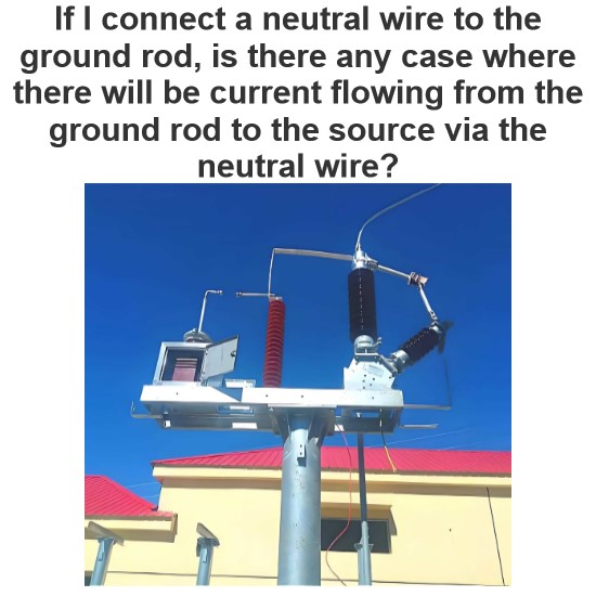
What happens when you connect the neutral wire to the ground rod?
Ideal Electrical System (Under Normal Conditions)In an ideal electrical system with proper wiring and no faults, the neutral wire is connected to the ground at the main service panel. This connection is made to establish a reference point for the electrical system. However, in normal operation, current should not flow from the ground rod to the source via the neutral wire.The neutral wire is designed to carry the return current from the load back to the source in a normal circuit. The ground rod
Encyclopedia
10/04/2024
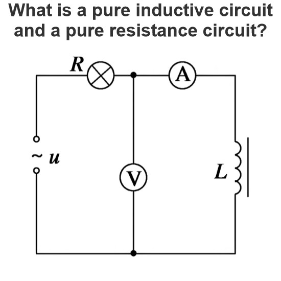
What is a pure inductive circuit and a pure resistance circuit?
Pure inductance circuit and pure resistance circuit are two basic circuit models, which respectively represent the ideal case of only inductance or only resistance components in the circuit. The following describes the two circuit models and their characteristics:Pure Resistor CircuitDefinitionA pure resistance circuit is a circuit that contains only resistance components (R) and no other types of components (such as inductors L or capacitors C). Resistance elements are used to represent the par
Encyclopedia
09/30/2024
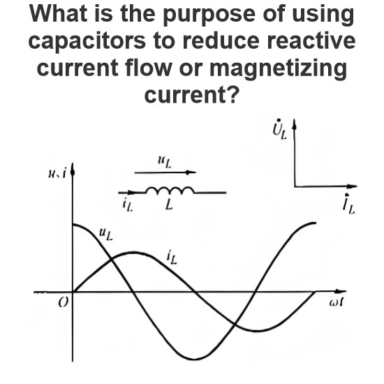
What is the purpose of using capacitors to reduce reactive current flow or magnetizing current?
The purpose of using capacitors to reduce reactive current (also known as magnetizing current) is mainly to increase the Power Factor (PF) of the power system. The power factor is a measure of the ratio of the actual energy used in an electrical system (active power) to the total apparent power (active power plus reactive power). Increasing the power factor helps to improve the efficiency and reliability of the power system. The following is a detailed explanation of the specific purpose of usin
Encyclopedia
09/30/2024
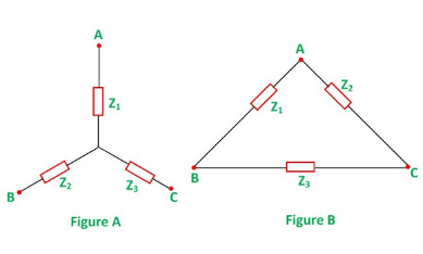
Star To Delta Conversion Formula
Three branches in an electrical network can be connected in numbers of forms but most common among them is either star or delta form. In delta connection, three branches are so connected, that they form a closed loop. As these three branches are connected nose to tail, they form a triangular closed loop, this configuration is referred as delta connection. On the other hand, when either terminal of three branches is connected to a common point to form a Y like pattern is known as star connection.
Electrical4u
03/13/2024
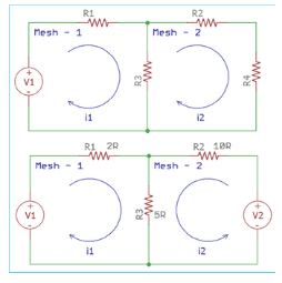
Single and Multi Mesh Analysis
The wordmeshmeans a smallest loop which is closed one and formed by using circuit components. The mesh must not have any other loop inside it. Like the other network analysis procedures, we can use Mesh Analysis to find out the voltage, current or power through a particular element or elements. Mesh analysis is based on Kirchhoff Voltage Law. We can use Mesh analysis only on planar circuits. The planar circuit is the one which is possible to draw on a plane surface in such a way that no branch p
Electrical4u
03/13/2024
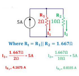
Voltage and Current Divider Rule
Current Division RuleWhen current flows through more than one parallel path, each of the paths shares a definite portion of the total current depending upon the impedance of that path.The definite portion of the total current shared by any of the parallel paths can easily be calculated if the impedance of that path and the equivalent impedance of the parallel system are known to us.The rule or formula derived from these known impedances to know the portion of total current through any parallel p
Electrical4u
03/13/2024
Nodal Analysis in Electric Circuits
Definition of Nodal AnalysisNodal analysis is a method that provides a general procedure for analyzing circuits using node voltages as the circuit variables. Nodal Analysis is also called the Node-Voltage Method.Some Features of Nodal Analysis are as Nodal Analysisis based on the application of theKirchhoff’s Current Law(KCL). Having ‘n’ nodes there will be ‘n-1’ simultaneous equations to solve. Solving ‘n-1’ equations all the nodes voltages can be obtained. The number of non reference nodes is
Electrical4u
03/13/2024
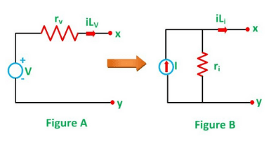
Source Transformation Technique
What is a Source Transformation?Anelectrical source transformation(or just ”source transformation”) is a method for simplifying circuits by replacing a voltage source with its equivalent current source, or a current source with its equivalent voltage source. Source transformations are implemented usingThévenin’s theoremandNorton’s theorem.Source transformation is a technique used to simplify an electric circuit.We’ll illustrate how this is done with an example.Let’s take a simple voltage source
Electrical4u
03/13/2024
Network Analysis or Circuit Analysis
Network Analysis is a process by which we can calculate different electrical parameters of a circuit element connected in an electrical network. An electrical circuit or network can be complicated too and in a complicated network, we have to apply different methods to simplify the network for determining the electrical parameters. The circuit elements in a network can be connected in different manners, some of them are in series and some of them in parallel. The circuit elements are resistors, c
Electrical4u
03/13/2024
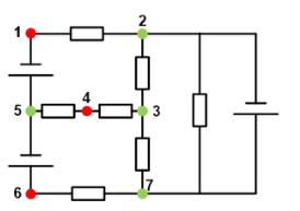
Essential Nodes And Essential Branches
What is an Essential Node?A node is defined as a point where two or more circuit elements are connected. An essential node is a particular type of node where three or more elements are connected. An essential node is a useful node to consider in circuit analysis.For example, in the below circuit, there is a total of seven nodes. Out of these seven nodes, there are four essential nodes that have been marked in green. The remaining three regular nodes have been marked in red.What is an Essential B
Electrical4u
03/13/2024
1
2
Source professional electrical partners, experts, and explore smart grid & energy solutions.
Inquiry
Send Now
Download
Experts Electrical is dedicated to serving the personnel in the global power industry.
Join Experts Electrical, not only can you discover power equipment and power knowledge, but also canhnd like - minded friends!