Single and Multi Mesh Analysis
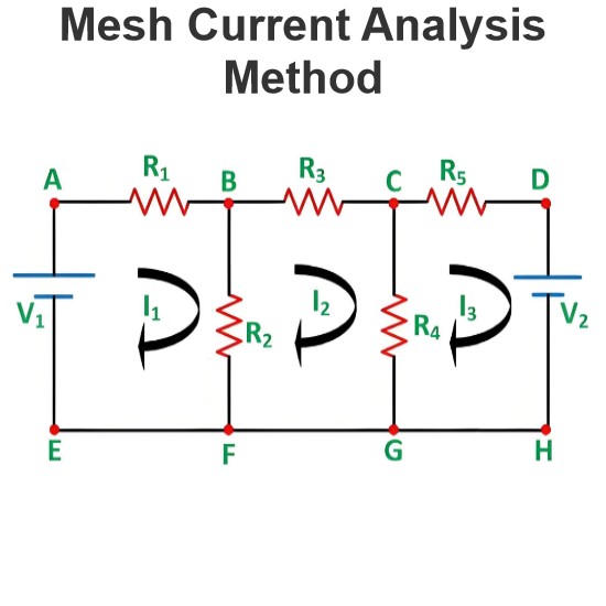
The word mesh means a smallest loop which is closed one and formed by using circuit components. The mesh must not have any other loop inside it.

Like the other network analysis procedures, we can use Mesh Analysis to find out the voltage, current or power through a particular element or elements. Mesh analysis is based on Kirchhoff Voltage Law. We can use Mesh analysis only on planar circuits. The planar circuit is the one which is possible to draw on a plane surface in such a way that no branch passes over or under any other branch. This circuit does not contain any branch which passes over or under any other branch.
Single Mesh
If in a closed circuit the number of mesh is only one, then that types of circuits are known as single meshed circuits.

In these types of analysis, the current or voltage across any element can be found out directly by using Ohm’s law. However, if the circuit elements are in parallel then also we can convert them into a single mesh by using the law of parallel combinations of the circuit elements.
Multi Mesh
The circuit, which has more than one mesh, is known as multi meshed circuit. The analysis of multi meshed circuit is somewhat difficult as compared to that of single meshed circuit.

If you would prefer a video explanation, we go over an example in the video below:
Steps for Mesh Analysis
The steps followed in mesh analysis are very simple, they are as follows-
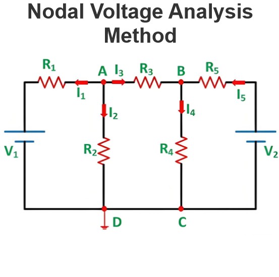
Frst we have to determine whether the circuit is planar or non planar. If it is a non planar circuit, we have to perform other methods of analysis such as nodal analysis.
Then we have to count the number of meshes. The number of equations to be solved is same as the number of meshes.

Then we label each of the mesh currents according to the convenience.

We write KVL equation for each of the meshes. If the element lies between two meshes then we calculate the total current flowing through the element by considering two meshes. If the direction of two mesh currents is same then summation of currents is taken as the total current flowing through the element and if the direction is opposite then the difference of mesh currents is taken. In second case the current in the mesh under consideration is taken as the greatest among all the meshes currents and the procedure is followed.
For mesh ABH, the KVL is

For mesh BCF, the KVL is

For mesh CDEF, the KVL is

For mesh BFG, the KVL is

For mesh BGH, the KVL is

Organize the equation according to the mesh currents.
Solve the mesh equations for i1, i2, i3, i4, and i5.
If any dependent source is there in the circuit or any unknown other than mesh currents, express that source in the suitable mesh currents.
Disadvantages of Mesh Analysis
We can use this method only when the circuit is planar, otherwise the method is not useful.
If the network is large then the number of meshes will be large, hence, the total number of equations will be more so it becomes inconvenient to use in that case.
Conclusion of Mesh Analysis
Though, it has some disadvantages, this method is a very powerful tool which may be used in circuit analysis. It is a widely used method in case of a small network, containing small number of meshes. It is so because the method is simple, easy to understand and gives quick results if the network is small.
Source: Electrical4u.
Statement: Respect the original, good articles worth sharing, if there is infringement please contact delete.
Electrical4U is dedicated to the teaching and sharing of all things related to electrical and electronics engineering.


