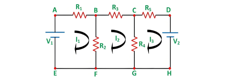
- R1, R2, R3, R4, and R5 represent various resistances.
- V1 and V2 are voltage sources.
- I1 is the current flowing in mesh ABFEA.
- I2 is the current flowing in mesh BCGFB.
- I3 is the current flowing in mesh CDHGC.
- For simplicity in network analysis, the current direction is assumed to be clockwise in all meshes.
Steps for Solving Networks via Mesh Current Method
Using the circuit diagram above, the following steps outline the mesh current analysis process:
Step 1 – Identify Independent Meshes/Loops
First, identify the independent circuit meshes. The diagram above contains three meshes, which are considered for analysis.
Step 2 – Assign Circulating Currents to Each Mesh
Assign a circulating current to each mesh, as shown in the circuit diagram (I1, I2, I3 flowing in each mesh). To simplify calculations, it is preferable to assign all currents in the same clockwise direction.
Step 3 – Formulate KVL Equations for Each Mesh
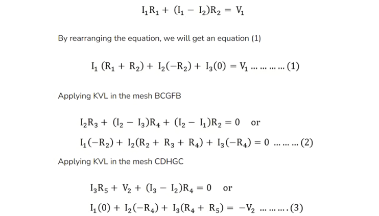
Since there are three meshes, three KVL equations will be derived:
Applying KVL to Mesh ABFEA:
Step 4 – Solve Equations (1), (2), and (3) simultaneously to obtain the values of currents I1, I2, and I3.
With the mesh currents known, various voltages and currents in the circuit can be determined.
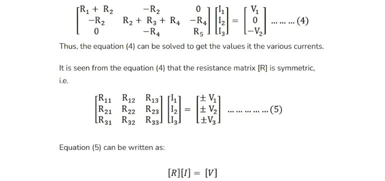
Matrix Form
The above circuit can also be solved using the matrix method. The matrix form of Equations (1), (2), and (3) is expressed as:
Where,
- [R] is the mesh resistance
- [I] is the column vector of mesh currents and
- [V] is the column vector of the algebraic sum of all the source voltages around the mesh.
This is all about the mesh current analysis method.