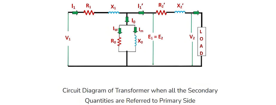
Equivalent Circuit of a Transformer

Edwiin
06/03/2025

The equivalent circuit diagram of any device can be extremely useful for predicting how the device will behave under different operating conditions. It is essentially a circuit - based depiction of the equations that describe the device's performance.
The simplified equivalent circuit of a transformer is constructed by representing all of the transformer's parameters on either the secondary side or the primary side. The equivalent circuit diagram of the transformer is presented below:

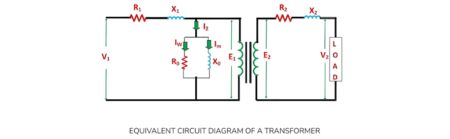
Let the equivalent circuit of a transformer be considered, with a transformation ratio K = E2/E1.The induced electromotive force E1 is equivalent to the primary applied voltage V1 minus the primary voltage drop. This voltage gives rise to the no - load current I0 in the primary winding of the transformer. Since the value of the no - load current is extremely small, it is often neglected in many analyses.Consequently,  I1I1. The no - load current I0 can be further decomposed into two components: the magnetizing current Im and the working current Iw.These two components of the no - load current are a result of the current drawn by a non - inductive resistance R0 and a pure reactance X0, across which the voltage is E1 (or equivalently, V1primary voltage drop).

The terminal voltage V2 across the load is equal to the induced electromotive force E2 in the secondary winding minus the voltage drop in the secondary winding.
Equivalent Circuit with All Quantities Referred to the Primary Side
In this scenario, to construct the equivalent circuit of the transformer, all parameters need to be referred to the primary side, as depicted in the figure below:

The following are the values of resistance and reactance given below

Secondary resistance referred to the primary side is given as:

The equivalent resistance referred to the primary side is given as:

Secondary reactance referred to the primary side is given as:

The equivalent reactance referred to the primary side is given as:

Equivalent Circuit with All Quantities Referred to the Secondary Side
The following is the equivalent circuit diagram of the transformer when all parameters are referred to the secondary side.

The following are the values of resistance and reactance given below

Primary resistance referred to the secondary side is given as

The equivalent resistance referred to the secondary side is given as

Primary reactance referred to the secondary side is given as

The equivalent reactance referred to the secondary side is given as

Simplified Equivalent Circuit of Transformer
Since the no-load current I0 typically accounts for only 3 to 5% of the full-load rated current, the parallel branch comprising resistance R0 and reactance X0 can be omitted without introducing significant errors in analyzing the transformer's behavior under loaded conditions.
Further simplification of the transformer's equivalent circuit is achieved by neglecting this parallel R0-X0 branch. The simplified circuit diagram of the transformer is as follows:

Edwiin

Inquiry
Download
Experts Electrical is dedicated to serving the personnel in the global power industry.
Join Experts Electrical, not only can you discover power equipment and power knowledge, but also canhnd like - minded friends!