Transformer Operation Under Load Conditions
When a transformer is under load, its secondary winding connects to a load, which can be resistive, inductive, or capacitive. A current I2 flows through the secondary winding, with its magnitude determined by the terminal voltage V2 and load impedance. The phase angle between the secondary current and voltage depends on the load characteristics.
Explanation of Transformer Load Operation
The operational behavior of a transformer under load is detailed as follows:
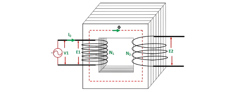
When the transformer secondary is open-circuited, it draws a no-load current from the main supply. This no-load current induces a magnetomotive force N0I0, which establishes a flux Φ in the transformer core. The circuit configuration of the transformer under no-load conditions is illustrated in the diagram below:

Transformer Load Current Interaction
When a load connects to the transformer secondary, current I2 flows through the secondary winding, inducing a magnetomotive force (MMF) N2I2. This MMF generates flux ϕ2 in the core, which opposes the original flux ϕ per Lenz's law.

Phase Difference and Power Factor in Transformer
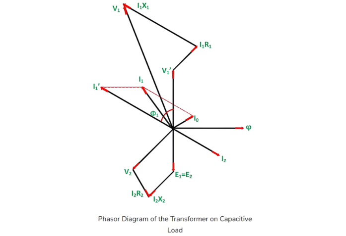
The phase difference between V1 and I1 defines the power factor angle ϕ1 on the transformer's primary side. The secondary-side power factor depends on the load type connected to the transformer:
- For an inductive load (as shown in the phasor diagram above), the power factor is lagging.
- For a capacitive load, the power factor is leading.
The total primary current I1 is the vector sum of the no-load current I0 and the counter-balancing current I'1, i.e.,

Phasor Diagram of Transformer with Inductive Load
The phasor diagram of an actual transformer under inductive loading is illustrated below:
Steps to Construct the Phasor Diagram
-
Take flux Φ as the reference.
-
Induced emfs E1 and E2 lag the flux by 90°.
-
The primary applied voltage component balancing E1 is denoted as V'1 (i.e., V'1 = -E1).
-
No-load current I0lags V'1 by 90°.
-
For a lagging power factor load, current I2 lags E2 by angle ϕ2.
- Winding resistance and leakage reactance cause voltage drops, making the secondary terminal voltage:V2 = E2 −(voltage drops)
- I2R2 is in phase with I2.
- I2X2 is orthogonal to I2.
- Primary current I1 is the phasor sum of I'1 and I0, where I'1 = -I2.
- Primary applied voltage:V1 = V'1 + (primary voltage drops)
- I1R1 is in phase with I1.
- I1X1 is orthogonal to I1.
- The phase difference between V1 and I1 defines the primary power factor angle ϕ1.
- Secondary power factor:
- Lagging for inductive loads (as in the phasor diagram).
- Leading for capacitive loads.

Steps to Draw Phasor Diagram for Capacitive Load
-
Take flux Φ as the reference.
-
Induced emfs E1 and E2 lag the flux by 90°.
-
The primary applied voltage component balancing E1 is denoted as V'1 (i.e., V'1 = -E1).
-
No-load current I0 lags V'1 by 90°.
-
For a leading power factor load, current I2 leads E2 by angle ϕ2.
-
Winding resistance and leakage reactance cause voltage drops, making the secondary terminal voltage:V2 = E2 −(voltage drops)
- I2R2 is in phase with I2.
- I2X2 is orthogonal to I2.
-
Counter-balancing current I'1 = -I2(equal in magnitude, opposite in phase to I2).
-
Primary current I1 is the phasor sum of I'1 and I0:I1=I1′+I0
-
Primary applied voltage V1 is the phasor sum of V'1 and primary voltage drops:V1 = V'1 +(primary voltage drops)
- I1R1 is in phase with I1.
- I1X1is orthogonal to I1.
-
Power factor angles:
- The phase difference between V1 and I1 defines the primary power factor angle ϕ1.
- The secondary power factor (leading for capacitive loads) depends entirely on the connected load type.