Network Analysis or Circuit Analysis
Network Analysis is a process by which we can calculate different electrical parameters of a circuit element connected in an electrical network. An electrical circuit or network can be complicated too and in a complicated network, we have to apply different methods to simplify the network for determining the electrical parameters. The circuit elements in a network can be connected in different manners, some of them are in series and some of them in parallel. The circuit elements are resistors, capacitors, inductors, voltage sources, current sources etc. Current, voltage, resistance, impedance, reactance, inductance, capacitance, frequency, electric power, electrical energy etc are the different electrical parameters we determine by network analysis. In short, we can say, an electrical network is the combination of different circuit elements and the network analysis or circuit analysis is the technique to determine the different electrical parameters of those circuit elements.
Graph of an Electrical Network
When we replace all the circuit elements of an electrical network by hand-drawn lines, then the figure is known as the graph of the network. The figure – 2 below shows the graph of the above network in figure – 1.
The line represents the circuit element is called the branch of a network. The point where two or more branches meet is called node of the network. The direction of current through the element is represented by arrowhead drawn on the branch. The direction of the current in a graph can be considered arbitrarily. When we draw a graph of a network with the direction of current (the direction may be arbitrary) in each of the branches, the graph is called oriented graph of the network. The figure – 3 below shows the oriented graph of the above network in figure – 1.
When an active network is represented as a passive network through a graph by removing the voltage and current sources then the graph is known as the oriented topological graph of the network. The voltage source is removed by replacing it with a short circuit and the current source is removed by replacing it with an open circuit. The above figure – 4 shown an electrical network with both voltage source and current source. The figure – 5 below shows the oriented topological graph of the network in figure – 4.
Definition of Terms used in Network Analysis
Branch
Each hand drawn line in a graph which represents the path for flowing of current is called branch.
Node
The end point of the branch where other branches meet is called a node.
Subgraph
This is a subset of branches of a graph.
Tree
The tree is a subgraph which contains all nodes of the graph but does not form any closed circuit. If the graph has n number of nodes, the tree will have (n – 1) number of branches. The branches of a tree are referred to as twigs. Hence a tree can also be referred to as a set of twigs.
Cotree
The cotree is a subgraph which contains all those branches which are not included in a tree. The cotree is the complement of a tree.
Equivalent Circuit
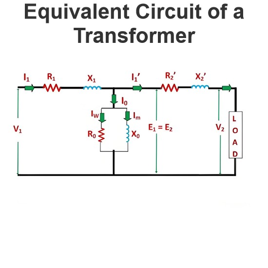
The main step of network analysis is to simplify comparatively complex network to its simplified form. It may normally be done by combining impedances in series and parallel. Sometimes it requires to transform some or all of the voltage sources of the network to current source and vise versa. If we consider any two terminals of an active network, obviously there would be a voltage across the terminals and current through the terminals. After simplification of the network, across these two terminals, the voltage and current in respect of the terminals remain unaltered from the original one. Although the structure of the network has been changed significantly. The original circuit (or network) and the simplified circuit (or network) are called equivalent circuit of each other. In case of a passive network, the impedance across any two reference terminal of the network remains same after simplifying the network.
Series and Parallel Circuit
During network analysis most frequently done activities are combining series and parallel circuit elements.
If n number of resistances are connected in series, the value of equivalent resistance would be,
If n number of resistances are connected in parallel, the value of equivalent resistance would be,
If n number of inductances are connected in series, the value of equivalent inductance would be,
If n number of inductances are connected in parallel, the value of equivalent inductance would be,
If n number of capacitances are connected in series, the value of equivalent capacitance would be,
If n number of capacitances are connected in parallel, the value of equivalent capacitance would be,
If n number of impedances are connected in series, the value of equivalent impedance would be,
If n number of impedances are connected in parallel, the value of equivalent impedance would be,
Star Delta Transformation
In case of two terminal network the impedances between the ports can easily be simplified by the series-parallel combination of the impedances. If the number of terminals in a network is more than two then the equivalent impedance between the terminals may not be solved by simple series and parallel combination of the impedances. Let us consider three terminal network. The impedances or any other similar parameters between the ports are either star connected or delta connected. The delta connected network can be converted into a star connected network and vice versa. During network analysis, we have to transform either delta to star or star to delta for simplifying the network. Let us consider one three terminal network formed by three impedances Za, Zb, and Zc connected in star. Consider another three terminal network formed by three impedances Zab, Zbc, and Zca. If these two networks are equivalent to each other then the relationship between the impedances of star and delta would be as follows.
Electrical Source Transformation
Another essential step very often used during network analysis is source transformation. Often it becomes essential to convert current sources to voltage sources and voltage sources to curr,ent sources for simplification of complex electrical network. In reality a practical voltage source can be considered as an ideal voltage source in series with its internal resistance. In the same way, a practical current source can be considered as an ideal current source in parallel with its internal resistance. When a voltage source is connected with a circuit it imposes its the voltage across the terminals of the circuit and it delivers certain current to the circuit depending on the impedance of the circuit and series internal resistance of the source. A current source can be said equivalent of the voltage source when the current source delivers the same current to the circuit when connected across same terminals. It is found that the current of the current source would be short circuit current of the voltage source and the value of internal resistance is same as that of voltage source but connected in parallel instead of series. That means if we short two terminals of a voltage source, the current flowing through the device is the current of the equivalent current source. Similarly, when a current source is open circuited, the voltage appears across the open terminal of the source would be the voltage of the equivalent voltage source.
Voltage Current Division Rule
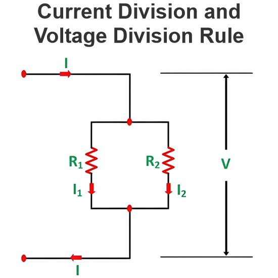
The often used techniques for network analysis are voltage and current division rule. Voltage division rule the process for calculating the voltage drop across a particular impedance among a series of impedances across a voltage source. Suppose, there are n number of impedances Z1, Z2, Z3 …..Zn connected in series across a voltage source of voltage Vs. Then the voltage drop across the impedance Z1 is, Here in the figure above we have considered impedances as resistances but we can consider any other impedance parameters instead of resistance according to the requirement of the circuit.
Similarly, the voltage drop across any particular impedance Zi is given by
Let us take one current source of current Is connected across n number of parallel admittance Y1, Y2, Y3 …Yn.
The current passing through the admittance Y1 is expressed as
Similarly, the current passing through the admittance Yi is,
Nodal Analysis and Mesh Analysis
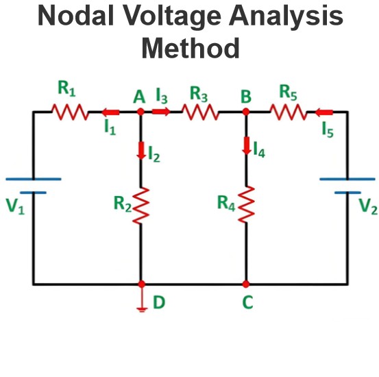
There are others two important methods used in network analysis. These are nodal analysis and mesh analysis. This is needless to say that these two methods are most common and most frequently used in network analysis. These two methods are nodal analysis and mesh analysis. The nodal analysis of a network mainly deals with Kirchhoff’s Current Law which says the current enters at a node is equal to the current leaves the node. In other words, the sum of all currents entering and leaving the node is equal to zero. If a node (the junction point of network branches) has n number of branches and I1, I2, I3 ….. In are the currents through the respective branches then,
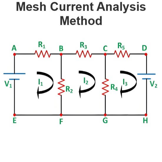
Mesh is the loop of a network which does not contain any other loop inside. The edges of a network mesh are formed by the branches of the network. As per mesh analysis, the sum of the voltage appears across each branch would be zero. That means along the edges of a mesh in any particular direction, the total of voltage gains is exactly equal to the total of voltage drops. This is nothing but Kirchhoff’s Voltage Law. If n number of branches form a mesh and the voltages across respective branches are V1, V2, V3, and Vn, then we can write,
Superposition Theorem
Another popular method of circuit solving during network analysis is superposition theorem. The method is applicable to the active network with more than one electrical sources. In superposition technique, we first have to remove all the sources by their internal impedance except one. The effect of this particular source on a branch of the network is first calculated. That means either voltage or current or both of that branch are calculated for that connected source in the network. Then we remove the source keeping its internal impedance at the place and reconnect the second source in place in the network. Now we have to calculate the required parameters of the same branch. In this way, we have to reconnect and remove all the sources one by one and calculate the required parameters each time. At last by summing the effects with the sign of all the individual source on the branch we get the cumulative effect on the branch when all the sources are connected to the network.
Norton Theorem
Concept of Norton Theorem is quite simple. Consider any branch in an electrical network. If the network is active, there must be certain current flowing through the branch. The origin of the current is the active network itself and the amount of current flowing through the brach is due to the equivalent impedance of the network and the impedance of the branch itself. As the rest of the network is supplying current to the branch, the network can be considered as an ideal current source of the current if the branch is short-circuited and with the equivalent impedance of the network connected in parallel to the source. The process of simplifying a network to an equivalent current source was developed by Edward Lawry Norton and is known as Norton Theorem.
Thevenin Theorem
The concept of Thevenin Theorem is similar to that of Norton Theorem, but here the entire active network is considered as a voltage source across the branch. The voltage of the source is the open circuit voltage of the network across the branch and the impedance of the source connected in series is the equivalent impedance of the network across the branch. The process of simplifying an active network to a single voltage source was developed by Leon Charles Thevenin.
Maximum Power Transfer Theorem
In a resistive active network, when the equivalent resistance of the network across a pair of terminals is exactly equal to the resistance of the branch connected across the terminals, maximum power would be transferred to the resistive branch from the network. The networks which are not fully resistive the Maximum Power Transfer Theorem can be defined in the following statement. In an active network, when the equivalent impedance of the network across a pair of terminals is complex conjugate of the impedance of the branch connected across the terminals, maximum power would be transferred to the branch from the network.
Source: Electrical4u.
Statement: Respect the original, good articles worth sharing, if there is infringement please contact delete.
Electrical4U is dedicated to the teaching and sharing of all things related to electrical and electronics engineering.


