| Brand | Vziman |
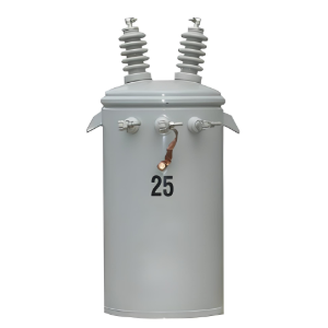
| Model NO. | 5-167 kVA single-phase overhead transformer |
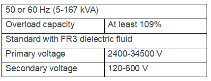
| Rated frequency | 50/60Hz |
| Primary voltage | 2400-34,500 V |
| Secondary voltage | 120-600 V |
| Capacity range | 5-167 kVA |
| Series | D-50 |
Descripton:
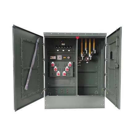
The single-phase overhead transformer ANSI boasts excellent load management performance, enabling it to handle load growth and temporary overloads with ease, without shortening the service life of the insulation system. The transformer's robust overload capacity allows power companies to operate stably under conditions of at least 109% of the rated load. Additionally, its compact and lightweight structural design further enhances the cost-effectiveness of the equipment and the efficiency of space utilization.
Performance and Design Advantages: This transformer is designed with the core objectives of enhancing performance and extending the insulation lifespan. It features a compact size and a lightweight design, and demonstrates outstanding performance in terms of safety and sustainability.
Optimization of the Insulation System: With excellent control over humidity and thermal stress, it effectively prolongs the service life of the insulation system and significantly enhances operational reliability.
Advanced Insulation Technology: Equipped with an advanced high-temperature insulation system, it integrates thermally upgraded kraft paper and FR3 dielectric fluid, and is paired with an optimized design of the core and coils, achieving technological upgrades.
Rich Specifications and Options: It provides a single-phase pole-mounted design with a power range of 5 - 167 kVA, and offers two temperature rise specifications of 75°C AWR and 65/75°C AWR to meet diverse requirements.
High-efficiency Advantages: The 75°C Average Winding Rise (AWR) configuration of the PEAK transformer can achieve the same power ratings as devices rated at 65°C AWR that are larger in size and heavier in weight, realizing high efficiency and compactness.
Outstanding Overload Capacity: The PEAK transformer with a 65/75°C slash rating has a nameplate overload capacity while having a size similar to that of traditional transformers, ensuring operation under special working conditions.
Compliance with High Standards: Its performance fully meets or exceeds industry standards such as ANSI and NEMA, and also satisfies the energy efficiency requirements of DOE, ensuring reliable quality.
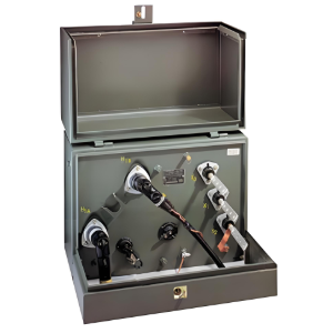
Flexible Protection Design: It supports two design schemes, namely traditional and CSP, and provides diverse overcurrent protection options to meet the protection needs of different application scenarios.
Reliable Material Selection: The core and coils are carefully designed with the aim of achieving high reliability and a low on-site failure rate, and two materials, grain-oriented steel and amorphous steel, are provided for users to choose according to their needs.
Technical Parameters:
Meets or exceeds ANSI, NEMA and DOE2016 standards
IEEE, C57.12.00, C57.12.20, C57.12.31, C57.12.35, C57.12.90, C57. 91 and C57.154
NEMA standards, NEMA TR 1 (R2000)
Department of Energy Efficiency Standard, 10 CFR Part 431
Tank coating exceeds IEEE Std C57.12.31-2010 standard
Cover with a minimum dielectric strength of 8 kV
FR3 fluid
Cores and coils designed for high reliability and low field failure rates: Available in grain-oriented electrical or amorphous steel
Heavy-duty lifting lugs and hanger brackets per ANSI requirements up to 4500 lbs
The transformer shall be designed in accordance with this specification and shall have an Average Winding Rise (AWR) of one of the following:
55/75 °C, 65/75 °C, 75 °C
The applicable AWR rating shall be specified on the inquiry
The transformer shall be designed in accordance with this specification and shall have one of the following kVA ratings:
5, 10, 15, 25, 37.5, 50, 75, 100, 167
The applicable kVA rating shall be specified on the inquiry
Quality System ISO 9001 certified