• Single-phase pad-mounted transformers with protective functions
Single-phase pad-mounted transformers with protective functions
discuss personally
Model
ZGS
Basic info
Brand Vziman
Model NO. Single-phase pad-mounted transformers with protective functions
Rated frequency 50/60Hz
Primary voltage 2400-19920 V
Secondary voltage 120-600 V
Capacity range 10-167 kVA
Series ZSG
Product Detail

Descripton:

The Completely Self-Protection (CSP) single-phase pad-mounted transformer is designed with the core objective of achieving excellent performance. It integrates a directly connected primary surge arrester, a MagneX arc extinguishing chamber, or a secondary circuit breaker with a built-in primary voltage fuse. There is no need to install additional independent protective equipment, which significantly reduces the installation cost.
The power range of this series of transformers covers 10 - 75 kVA. When equipped with a MagneX arc extinguishing chamber, the power range can be expanded to 10 - 167 kVA, and its performance fully meets or even exceeds relevant standards such as ANSI and NEMA.
In addition, the CSP transformer supports two types of filling media. It can be filled with standard electrical-grade mineral insulating oil or FR3 liquid with excellent fire resistance, flexibly adapting to different usage scenarios.

Features:

  • Equipped with an internal overcurrent device and a surge arrester, it can achieve efficient overvoltage protection without the need for external independent protective components. For secondary faults and overloads, it can provide dual reliable protection through a secondary circuit breaker with weak links or an optional MagneX arc extinguishing chamber.
  • It supports the free choice of two filling media: FR3 fireproof insulating oil, which greatly enhances the fire safety level; or standard electrical-grade mineral oil to meet regular usage requirements. The product performance comprehensively surpasses industry standards and performs excellently in terms of ANSI specifications, NEMA standards, and DOE energy efficiency requirements.
  • The core and coils are deeply optimized in design. Aiming to achieve high reliability and a low failure rate, it offers two materials, grain-oriented steel and amorphous steel, to adapt to different performance needs. Both the high-voltage and low-voltage bushing terminals are tinned, making them compatible with aluminum and copper conductors to ensure stable and reliable electrical connections.
  • The exterior design takes into account both functionality and aesthetics, offering two style options: the MaxiShrub style equipped with an ANSI Type-1 front panel, or the Shrubline style with an ANSI Type-2 front panel. Both adopt a low-profile design and can better blend into the surrounding environment.

Technical Parameters:

Specifications:

  • Meet or exceeds ANSI, NEMA and DOE2016 standards
  • IEEE standards C57.12.00, C57.12.38, C57.12.28, C57.12.35, C57.12.90, C57. 91 and C57.154
  • NEMA standards, NEMA TR 1 (R2000)
  • Department of Energy Efficiency Standard, 10 CFR Part 431
  • Tank coating exceeds IEEE Std C57.12.28-2005 and C57.12.29-2005 standards (stainless steel units only)
  • Full compliance with IEEE Std C57.12.28-2005 standard enclosure integrity requirements
  • FR3 fluid or electrical grade mineral oil
  • Cores and coils designed for high reliability and low field failure rates: Available in grain-oriented electrical or amorphous steel
  • The transformer shall be designed in accordance with this specification and shall have an Average Winding Rise (AWR) of one of the following:
  • 55 °C, 55/65 °C, 65 °C
  • The applicable AWR rating shall be specified on the inquiry
  • The transformer shall be designed in accordance with this specification and shall have one of the following kVA ratings:
  • 10, 15, 25, 37.5, 50, 75, 100, 167
  • The applicable kVA rating shall be specified on the inquiry
  • Quality System ISO 9001 certified
Know your supplier
Vziman
Zhejiang Vziman Electric Group Co., Ltd. is a high-tech enterprise specializing in R&D, manufacturing, and service of power electrical equipment. Committed to innovation, quality, and customer satisfaction, it supplies smart solutions for global power sectors, covering grid construction, new energy, and industrial distribution. Core Business • Switchgear (GIS, circuit breakers, Recloser, Load break switch) 
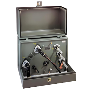
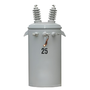
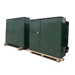
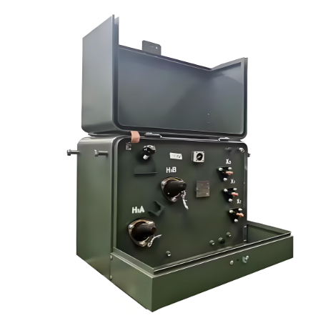
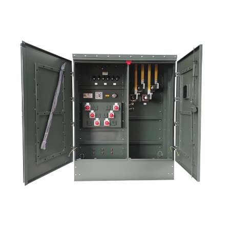
• Distribution equipment (transformers, RMU, smart terminals) • Power automation systems • Engineering services (installation, maintenance, consulting) Technical Strength • Provincial R&D center, multiple patents • Modern production, ISO/GB/IEC/CE/UL certified • High capacity, large-scale delivery support Market & Vision Serves State Grid, Southern Grid, and global projects (Asia, Africa, Europe, etc.). Aims to lead in smart grids and new energy, promoting sustainable energy development.
Main Categories
High voltage
Business Type
Design/Manufacture/Sales
Highest Annual Export (USD)
$150000000
Professional Experience
3 years
Workplace
10000m²
占位
占位
Related Products
Related Knowledges
What is Transformer Vector Groups?
Transformer Vector Group DefinitionThe transformer vector group denotes the phase difference between the primary and secondary sides of a transformer, while also defining the arrangement of high-voltage and low-voltage windings in three-phase transformers. Vector groups are determined by the connection configurations of three-phase transformers, which can be categorized into four main groups based on the phase difference between corresponding line voltages of the high-voltage and low-voltage sid
Edwiin
06/02/2025
What is a Pure Resistive AC Circuit?
Pure Resistive AC CircuitA circuit containing only a pure resistanceR(in ohms) in an AC system is defined as a Pure Resistive AC Circuit, devoid of inductance and capacitance. Alternating current and voltage in such a circuit oscillate bidirectionally, generating a sine wave (sinusoidal waveform). In this configuration, power is dissipated by the resistor, with voltage and current in perfect phase—both reaching their peak values simultaneously. As a passive component, the resistor neither
Edwiin
06/02/2025
What is a Pure Capacitor Circuit?
Pure Capacitor CircuitA circuit comprising only a pure capacitor with capacitanceC(measured in farads) is termed a Pure Capacitor Circuit. Capacitors store electrical energy within an electric field, a characteristic known ascapacitance(alternatively referred to as a "condenser"). Structurally, a capacitor consists of two conductive plates separated by a dielectric medium—common dielectric materials include glass, paper, mica, and oxide layers. In an ideal AC capacitor circuit, the current
Edwiin
06/02/2025
Resonant Frequency
Resonant Frequency
In a series circuit, the resonant frequency condition occurs when the inductive reactance equals the capacitive reactance. Changing the supply frequency alters the values of XL = 2πfL and XC = 1/2πfC.As the frequency increases, XL rises whileXC falls. Conversely, a decrease in frequency causesXL to drop andXCto rise.To achieve series resonance, the frequency is tuned to fr(pointP in the curve below), whereXL = XC.At series resonance, when XL = XCWhere frdenotes the resonant frequency in he
Edwiin
06/02/2025
Current Division and Voltage Division Rule
Current Division RuleA parallel circuit functions as a current divider, where the incoming current splits among all branches while the voltage across each branch remains constant. The Current Division Rule is used to determine the current through circuit impedances, as illustrated by the circuit below:The currentI splits intoI1 andI2 across two parallel branches with resistancesR1 andR2, whereVdenotes the voltage drop across both resistances. As is known,Then the equation of the current is writt
Edwiin
06/02/2025
Mesh Current Analysis Method
The Mesh Current Analysis Method is utilized to analyze and solve electrical networks with multiple sources or circuits comprising numerous meshes (loops) containing voltage or current sources. Also known as the Loop Current Method, this approach involves assuming a distinct current for each loop and determining the polarities of voltage drops across loop elements based on the assumed direction of the loop current.In mesh current analysis, the unknowns are the currents in different meshes, and t
Edwiin
06/02/2025
×
Inquiry
Download
Experts Electrical is dedicated to serving the personnel in the global power industry.
Join Experts Electrical, not only can you discover power equipment and power knowledge, but also canhnd like - minded friends!
商品视频播放