| Brand | Vziman |
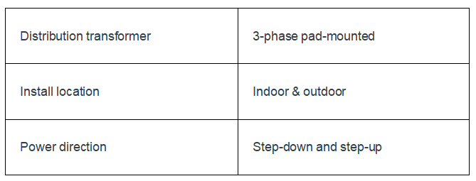
| Model NO. | 45-12000 kVA Three-phase pad-mounted transformers |
| Rated frequency | 50/60Hz |
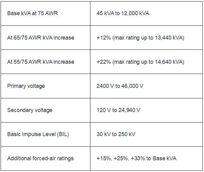
| Primary voltage | 2400V-46000V |
| Secondary voltage | 120V-24940V |
| Capacity range | 45kVA-12000kVA |
| Series | ZGS |
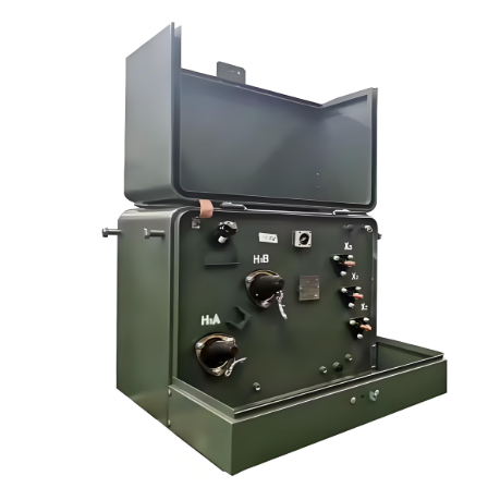
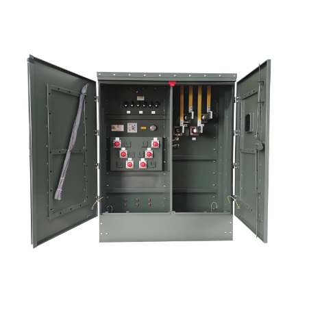
Descripton:
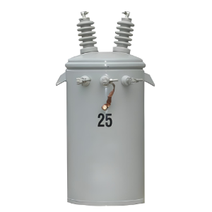
Three-phase pad-mounted transformers (ANSI )are sustainable, high-performance, and safety-first power solutions. Filled with FR3 environmentally friendly insulating fluid, they possess excellent flame-retardant properties. Their insulation system lifespan is 5 to 8 times longer than that of traditional mineral oil transformers, significantly extending the service cycle of the equipment, effectively reducing the replacement frequency, and achieving long-term and stable asset value.
Fire Safety Assurance:Build an unbreakable fire safety defense line, always maintaining an unparalleled record of zero fire accidents, and setting an industry benchmark for the safety of power operation.
Equipment Lifespan Advantage:Its outstanding durability far exceeds that of similar products. The service life of the equipment is three times that of traditional mineral oil transformers, greatly reducing replacement and maintenance costs and maximizing asset value.
Characteristics of Environmentally Friendly Oil:Adopt environmentally friendly transformer oil with a high flash point. It is not only easily biodegradable but also completely non-toxic and harmless. While ensuring stable power transmission, it minimizes the impact on the ecological environment.
Economic and Environmental Performance:The FR3 fluorinated fluid continuously delivers efficient and stable performance at an affordable cost, perfectly balancing economic efficiency and sustainability, and contributing to the construction of a green power ecosystem.
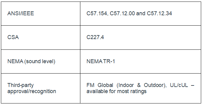
Standard Compliance:The fluid used strictly adheres to the dual stringent standards of ASTM D6871-03 and IEEE PC57.147, ensuring the reliability of product quality and performance from the source.
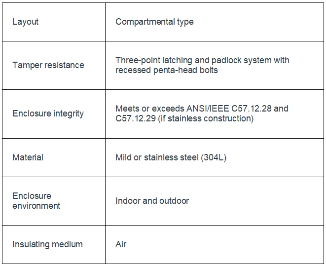
Customized Design:The innovative compartmentalized transformer adopts a highly flexible customized design concept, which can accurately meet the diverse needs and personalized specifications of customers and provide exclusive power solutions.
Technical Parameters: