CIS (Gas Insulated Switchgear) refers to a gas - insulated enclosed switchgear assembly. A busbar is a common pathway to which multiple devices are connected in parallel. In a CIS, the internal space of the busbar is relatively small, yet it operates under high voltage and current. Local discharge, if it occurs, can severely affect the inter - phase insulation and pose a significant threat to the safe and stable operation of the equipment. This article presents an analysis and solution of a local discharge fault in a CIS busbar, and introduces an improved fastening scheme for CIS busbar bolts for reference.
Fault Situation
A 220 kV CIS in a certain substation was put into operation on December 20, 2016. In March 2017, during a live detection of the substation, operation and maintenance personnel detected obvious very - high - frequency (VHF) signals on the busbar, preliminarily determining that there was a local discharge fault in the busbar.
When using a partial discharge detector (model PDT - 840MS) for live detection, the operation and maintenance personnel detected obvious VHF signals on the built - in sensor of the busbar between the 204 circuit breaker on the 220 kV side of the No. 4 main transformer and the 225 circuit breaker of the 220 kV Xinguo Line. The signals showed two distinct and symmetrical clusters, with a large discharge quantity. The maximum amplitude reached 67 dB, and abnormal internal discharge sounds could be heard on - site, preliminarily indicating the presence of local discharge in the equipment. The company arranged for the maintenance center to conduct re - measurement, and abnormal VHF and ultrasonic signals were detected simultaneously.
The ultrasonic detection showed that the peak value in the continuous mode was approximately 120 mV, with a certain 100 Hz frequency correlation, and the maximum value in the phase mode was about 70 mV. After analysis, it was determined that the floating discharge was caused by the vibration of the inter - phase insulation inside the 2B busbar gas chamber between the 204 circuit breaker bay on the 220 kV side of the No. 4 main transformer and the 225 circuit breaker bay of the 220 kV Xinguo Line.
Analysis of the Fault Causes
Load Statistics and Inspection of the Faulty Busbar Bay
Loads of the 220 kV Xinguo Line and the 204 circuit breaker of the No. 4 main transformer were statistically analyzed. The load of the 220 kV B - section busbar showed no significant change and did not exceed the rated value.
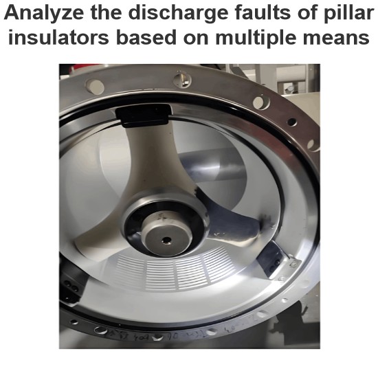
Maintenance personnel, together with the manufacturer's technicians, carried out a disassembly inspection of the busbar bay where local discharge occurred. This section of the busbar is 7 m long and has 6 inter - phase insulation supports inside. After disassembling the busbar, three loose bolts were found: the V - phase of the first inter - phase insulation component, the V - phase of the fifth inter - phase insulation component, and the W - phase of the sixth inter - phase insulation component. Among them, the first bolt was the loosest, which could be directly removed, and there was a large amount of dust around it.
Threads of the metal inserts on other inter - phase insulators showed no obvious damage, and the surface of the insulator material had no cracks, scratches, or abnormal depressions. Other parts of the three - phase conductors of other inter - phase insulators and other connection points showed no abnormalities. The tightening torques of the connection bolts between the other 15 inter - phase insulators and the conductors met the specified requirements.
Analysis and Verification
- Quality of Busbar Module Components and Installation. Upon inspection, the quality of the busbar duct shell and conductor complies with the technical quality requirements of the manufacturer's drawings. The straightness of the components themselves meets the shape tolerance requirements of the drawings. The insulators and their metal grading inserts are manufactured by casting and solidifying in a mold. During the factory assembly process, a special fixture is used to position the relative spatial positions of the three - phase conductors. However, the tightening torques of the connection bolts between the conductors and the insulators do not fully meet the manufacturer's requirements in some cases.
- When the busbar is in live operation, the three - phase currents are symmetrical, and each phase conductor is subjected to the same alternating electrodynamic force. The three phases are symmetrically distributed in space. The busbar conductor is a hollow conductor, which has a higher bending strength than conductors. Under normal installation, the three - phase conductors will not deviate towards any fixed angular position due to the electrodynamic force during operation.
- Mechanical Strength Calculation. The manufacturer calculates the connection strength of the fasteners and determines that the connection length between the external thread of the bolt and the internal thread of the insulator insert needs to be greater than the current design of 16 mm, and the thickness of the metal shim needs to be increased to at least 7 mm (currently 4 mm). This can meet the mechanical strength requirements under the condition of a single - bolt connection and an electrodynamic force of 10 kN during busbar short - circuit.
- Type Tests. Results of the 500 A/3 s thermal stability (short - time withstand current) test, 135 kA dynamic stability (peak withstand current) test, especially the temperature - rise test under a busbar current of 7 h/4000 A, show that there are no obvious mechanical loosening or abnormal connections after the tests. This indicates that the existing design for fastening the busbar conductors is reliable under type - test conditions.
Cause Determination
Through on - site inspection and theoretical analysis, the main cause of this fault is determined as follows: The tightening torques of the bolts during the manufacturer's assembly do not meet the standards, and the connection length of the bolts and the thickness of the shims cannot meet the operational requirements.
Treatment Scheme
Based on the results of on - site inspections and theoretical analyses, a new bolt - tightening scheme has been proposed to ensure the reliable operation of the busbar.
- Employ double - ended screws that are connected in a mating manner with the internal threads of the metal inserts of the annular insulators (on the side of the shorter thread of the screw). Apply Loctite 603 adhesive No. 2 to the surface of the external threads of the screw. Apply three longitudinal strips of Loctite 603 adhesive at intervals of approximately 120° along the circumference of the 24 - mm thread length, ensuring that the entire 360° surface of the thread is coated with the adhesive after screwing in. After the bolt is fully inserted, use special cleaning paper to remove any excess adhesive.
- Use self - locking/anti - loosening nuts in combination to effectively prevent the bolts from loosening. Adopt an integrated shim component with a thickness of 8 mm.
- Use a torque wrench to tighten the bolts, taking a value of 75 N·m, which is on the upper end of the (70±7) N·m range. To ensure that the torque of each bolt is up to standard, implement a system where one person works and another checks.
After the tightening is completed, use a vacuum cleaner, special cleaning paper, and alcohol to thoroughly clean the tightened areas and the cavity areas of the conductors.
On - Site Treatment
Double - ended bolts are used to enhance the tightening force of the bolts, and self - locking nuts are used to prevent the bolts from loosening due to electrodynamic forces during normal operation. The manufacturer carried out bolt modification work on this GIS busbar according to the above - mentioned scheme, and the results after the modification are satisfactory.