The Importance of Long-Distance Loop Resistance Testing in GIS and Its Practical Application

Echo
05/24/2025
Importance of Long - distance Loop Resistance Testing for GIS
Inspecting the Installation Quality of Electrical Equipment and the Integrity of the Loop
Inspecting the Installation Quality of Electrical Equipment and the Integrity of the Loop
In the handover tests of GIS, loop resistance testing plays a crucial role. This test is not only a key step in evaluating the installation quality of electrical equipment but also an important means to ensure the integrity and safety of the entire loop. Through precise testing and analysis, potential problems can be promptly identified and resolved, ensuring that GIS equipment can operate stably and reliably after being put into service.
Reflecting the Grounding Performance and Connection Quality of Equipment
Regularly testing the loop resistance value of GIS equipment is of great significance for promptly detecting and resolving issues such as grounding faults or poor contacts. Once an abnormal loop resistance value is detected, further inspection and maintenance should be carried out immediately to ensure that the grounding performance and connection quality of the equipment meet the standards. Testing the loop resistance can also provide important references for the maintenance and overhaul of GIS equipment. By analyzing historical test data, the changing trend of the equipment's grounding performance can be understood, potential problems can be predicted, and corresponding maintenance and overhaul plans can be formulated in advance. This can not only enhance the reliability of the equipment and extend its service life but also reduce production losses caused by equipment failures and lower safety risks.
Ensuring the Safe and Stable Operation of Equipment
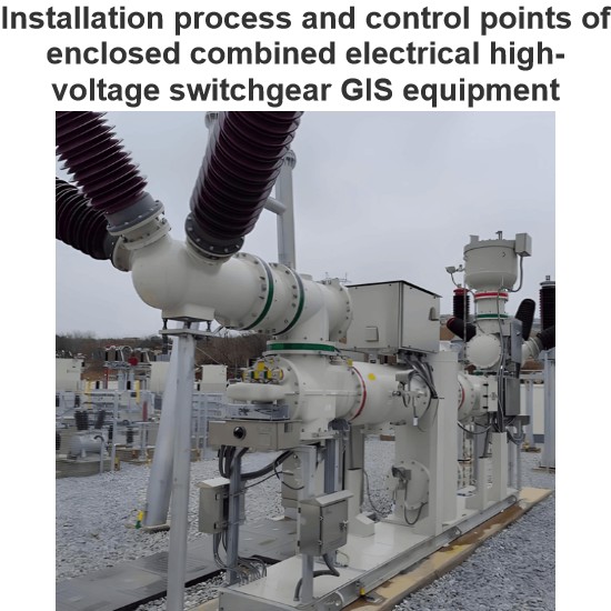
GIS equipment is enclosed in a thick metal casing, and its busbars (including branch busbars) are usually connected through plug - in structures such as plum - blossom contacts and strap - type contact fingers. The connection conditions at these joints cannot be accurately determined by the naked eye or even infrared temperature measurement. Therefore, long - distance loop resistance testing is of great significance for ensuring the safe and stable operation of equipment.
Detecting and Preventing Potential Safety Hazards
Due to factors such as vibration and temperature changes, problems such as loosening of internal connectors or poor contacts may occur in GIS equipment during operation. These problems may trigger equipment failures or accidents, posing a threat to the stable operation of the power system. Through long - distance loop resistance testing, these problems can be detected in a timely manner, and corresponding measures can be taken for handling, thereby preventing potential safety hazards.
Practical Application of Long - distance Loop Resistance Testing for GIS
Purpose of Long - distance Loop Resistance Testing for GIS
Purpose of Long - distance Loop Resistance Testing for GIS
The main purpose of long - distance loop resistance testing for GIS is to inspect the installation quality of electrical equipment, the integrity of the loop, as well as the grounding performance and connection quality of the equipment. Through testing, defects such as poor contacts caused by poor manufacturing, improper installation, or mechanical loosening due to vibration during operation can be promptly detected, avoiding accidents resulting from poor contacts.
Testing Principle
According to "Installation Engineering of Electrical Equipment Acceptance Criteria for Handover Tests of Electrical Equipment" (GB 50150 - 2016) and other relevant electrical safety and technical regulations, long - distance loop resistance testing of GIS is a crucial part of ensuring the safe and reliable operation of electrical equipment. In this process, the DC voltage - drop method is widely used because it can provide accurate and stable test results.
Test Preparation
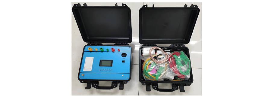
Before conducting long - distance loop resistance testing for GIS, sufficient preparatory work needs to be done. First, check the on - site safety measures to ensure the safety of the testing environment. Second, prepare the testing instruments, connect the resistance tester to the power supply, and calibrate it according to the instruction manual. Finally, inspect the testing circuit to ensure that the testing circuit has good contact with the grounding point of the equipment and is firmly fixed. The main unit of the testing instrument and all its accessories are shown in Figure 1.
Connecting the Test Circuit
Due to their high integration and safety features, GIS equipment is usually designed with dedicated grounding points. These grounding points are generally located at the bottom or side of the equipment and are marked with clear grounding signs for easy identification and operation by workers. The test circuit is typically made of highly conductive materials, such as copper or aluminum, to ensure smooth current flow. One end of the circuit needs to be equipped with a connector that matches the grounding point of the GIS equipment to ensure a firm connection without loosening.
Workers need to connect one end of the test circuit to the grounding point of the GIS equipment. During connection, it is necessary to ensure that the connector fits tightly with the grounding point, without any gaps or looseness, which can be achieved by using appropriate tools for tightening. At the same time, it is also necessary to check whether there are obvious oxidation or corrosion phenomena at the connection. If so, timely cleaning or replacement should be carried out.
Next, connect the other end of the test circuit to the current output terminal of the testing instrument. The testing instrument usually has multiple interfaces for connecting different types of test circuits and sensors. Workers need to select the interface that matches the current test requirements and ensure a firm connection between the test circuit and the interface.
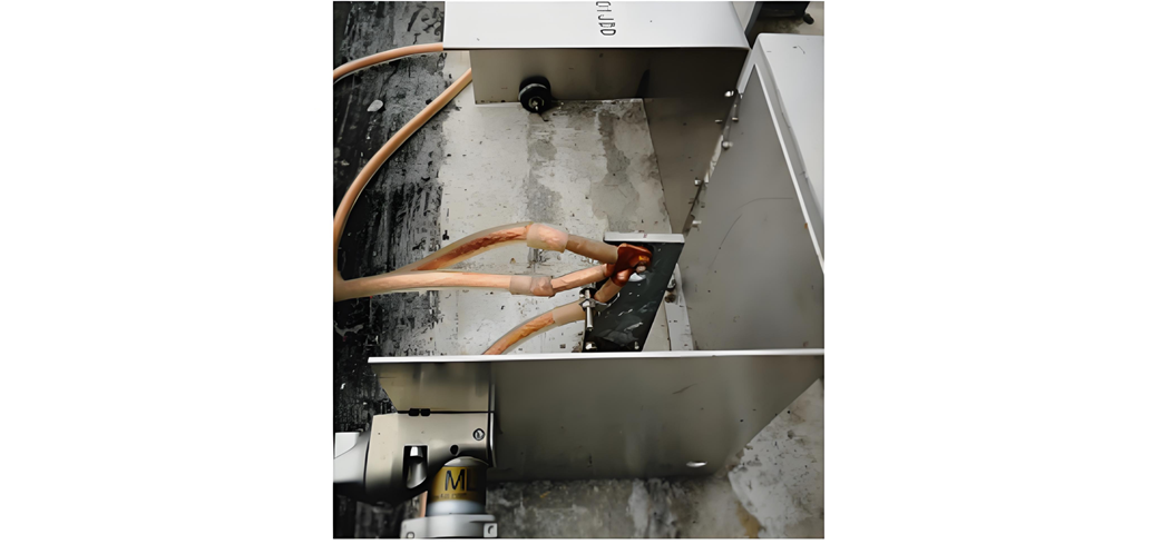
After the connection is completed, workers also need to conduct a series of checks and confirmations. Verify whether the test circuit is connected correctly, check for any open - circuit or short - circuit conditions; check whether the testing instrument has correctly set the test parameters and measurement range to ensure the accuracy and reliability of the test results; and also pay attention to checking the safety of the test site to ensure that no harm will be caused to personnel or equipment during the test. The connection of the test circuit is shown in Figure 2.
Setting Test Parameters
The tester needs to power on the testing instrument and locate the interface or menu for parameter - setting. Once the parameter - setting interface is found, the tester should set the parameters one by one according to the test requirements. First is the setting of the test current. The magnitude of the test current depends on the rated current of the GIS equipment and the test purpose. The tester must select an appropriate current value based on the test requirements and ensure that the testing instrument can stably output this current. When setting the current, attention should also be paid to the accuracy and stability of the current output to guarantee the accuracy of the test results.
Besides the test current, the test duration is also a crucial parameter. The length of the test duration depends on the test requirements and the characteristics of the GIS equipment. The tester needs to set an appropriate test duration according to the test requirements and ensure that the testing instrument can accurately time it. During the test, the tester should also pay attention to the start and end times of the test to ensure the integrity and accuracy of the testing process.
In addition, according to the test requirements, other parameters such as test frequency and waveform may need to be set. The setting of these parameters also needs to be selected and adjusted based on the test requirements and the characteristics of the GIS equipment.
Initiating the Test
After the preparatory work is completed, the tester initiates the testing instrument according to the predetermined operation procedure. During the startup process, the instrument will perform a self - check. After confirming that all functions are normal, the tester needs to set the test parameters, including the target current value and test duration.
The testing instrument will start sending current according to the set parameters. The current will be precisely controlled and flow through the grounding loop. The grounding loop is an essential part of the electrical system, which connects the metal casing or other conductive parts of the electrical equipment to the ground to ensure the safety of the equipment and personnel.
While the current is flowing through the grounding loop, the testing instrument will use advanced measurement techniques to monitor and record the magnitude of the loop resistance in real - time. The loop resistance is a vital indicator reflecting the performance of the grounding loop. Its magnitude directly affects the operational safety of the electrical equipment and the personal safety of personnel. Therefore, accurate measurement of the loop resistance is a very critical step in the test.
During the test, the tester will closely monitor the display and data changes of the testing instrument to promptly detect and handle any possible abnormal situations. Meanwhile, they will also conduct data analysis based on the test results to evaluate whether the performance of the grounding loop meets the requirements and formulate corresponding improvement measures accordingly.
Recording Test Results
Testers are required to record in detail basic test information, test parameters, test results, the test environment, and remarks. This facilitates a comprehensive understanding of the equipment's performance status and provides robust support for subsequent maintenance and improvement.
Analysis and Handling of Test Results
Based on the test results, the installation quality and loop integrity of GIS equipment can be evaluated. If the test results exceed the specified range, it indicates that the equipment has defects such as poor contact, necessitating further inspection and handling. Additionally, the grounding performance and connection quality of the equipment can be assessed according to the test results, providing a basis for equipment maintenance and overhaul.
Precautions
The connections between the test leads, the circuit breaker terminal block, and the tester should be tight and secure to ensure that the test current can flow smoothly through the grounding loop and accurate resistance values can be obtained. The test leads should not be tangled or disorganized but rather arranged in a simple and orderly manner to prevent interference and short - circuits between the leads, thereby ensuring the accuracy and safety of the test. Testers can sort and categorize the test leads in an orderly fashion before the test for easier operation and management during the test.
When testing three - phase electrical equipment, ensuring the basic balance of three - phase data is of utmost importance. Three - phase balance means that the three - phase currents, voltages, or other relevant parameters are approximately equal in value, which is fundamental to the normal operation of electrical equipment. Therefore, when a significant deviation in one - phase data is detected, even if the deviation is still within the acceptable range, testers should immediately stop the test and carefully check the wiring.
First, check whether the connection between the test leads and the equipment terminal block is firm and reliable, and whether there is any looseness or poor contact. If problems are found, immediate repairs should be carried out to ensure a tight and reliable connection. Also, check the internal wiring of the equipment, including inspecting components such as cables, busbars, and connectors inside the equipment for any damage, aging, or incorrect connections.
If such issues are detected, they should be promptly replaced or repaired to ensure normal and reliable internal electrical connections of the equipment. After eliminating wiring problems, if the deviation in one - phase data remains significant, it may be necessary to further inspect other parts of the equipment, such as the power supply, load, and control system, as problems in these parts can also cause abnormal one - phase data. By gradually troubleshooting and fixing these issues, the basic balance of three - phase data can be ensured, guaranteeing the normal operation of the electrical equipment.
To ensure the safe conduct of testing or maintenance work, when a current transformer (TA) is inserted into the measuring loop, the secondary winding of the TA must be short - circuited. Short - circuit operation is typically achieved by connecting a short - circuit link or short - circuit wire, which ensures that the current in the secondary winding can flow, thereby avoiding the generation of high voltage.
Conclusion
Long - distance loop resistance testing for GIS is one of the important means to ensure the safe and stable operation of GIS equipment. Through this testing, the grounding performance and connection quality of the equipment can be reflected, potential safety hazards can be detected and prevented, and the operating status and performance of the equipment can be evaluated.
In practical applications, it is necessary to strictly follow the testing methods and procedures and pay attention to relevant safety items and precautions. Through scientific testing and analysis, strong support can be provided for the preventive maintenance and fault diagnosis of GIS equipment, ensuring the safe and stable operation of the power system.
As an expert in the application and trends of electrical equipment, I have a profound mastery of knowledge in circuits, power electronics, etc. I possess a comprehensive set of abilities including equipment design, fault diagnosis, and project management. I can precisely grasp the industry's pulse and lead the development of the electrical field.