Installation process and control points of enclosed combined electrical high-voltage switchgear GIS equipment

Pre - installation Preparations for GIS Equipment
- The civil engineering, lighting, and decoration projects in the installation area must all be completed and pass the acceptance inspection.
- Professional supervisors are required to direct the hoisting during product installation.
- Ensure that the required lighting and power supply equipment can be used reliably before installation.
- An enclosed and lockable storage room should be set up near the work area at the installation site to store installation tools, parts, and other items, and a mobile tool cart should be equipped for transporting tools and parts.
- The installation area must be kept highly clean. The floor should be covered with floor leather, and the floor should be cleaned daily with a vacuum cleaner or mopped with a wet mop.
- A mobile power strip (380 V, 220 V) covering the entire installation area should be provided on - site.
- Personnel without permission are prohibited from entering the installation work area during product assembly.
Hazard Point 1: Electric Shock to Personnel
Preventive measures are as follows:
- Before work, the work supervisor should inform all workers about the live parts adjacent to the work site.
- Carefully check the maintenance scope and enter the work only after confirming it is correct.
- Ground both ends of the equipment maintenance section.
The decomposition products of SF₆ gas under the action of an electric arc are highly toxic and can seriously affect physical health upon contact. Preventive measures are as follows:
- When the GIS cylinder is opened, personnel should stand upwind and ventilate for 0.5 hours.
- Personnel in contact should wear protective clothing and masks.
Preventive measures are as follows:
- Recover and fill SF₆ gas, and assign a dedicated person to monitor the equipment instruments.
- Only when it is confirmed that the recovered pressure of SF₆ gas meets the requirements of the plan can the bolts connecting the cover plate or flange be loosened.
Responsibilities of GIS Equipment Manufacturers
- Provide technical documents related to installation.
- Offer technical guidance throughout the installation, adjustment, and testing processes.
- Inspect the assembled and cleaned internal components of the tank and conduct final quality verification.
- Provide items such as secondary wiring cables, cable tags, and terminal blocks from the local control cabinet to the product.
- Transport and remove the outer packaging of the product.
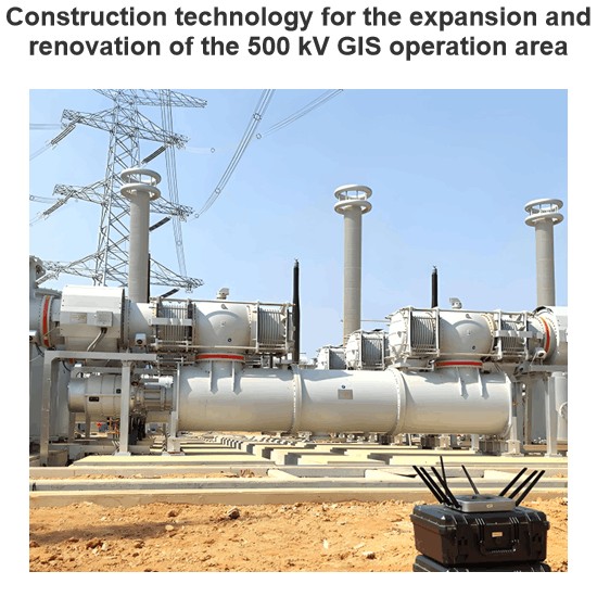
- Hoist and position the GIS equipment.
- Assemble, clean, and inspect the internal components of the tank.
- Conduct operations such as vacuum - pumping, gas - filling, leak - detection by wrapping, and micro - water detection.
- Fabricate and install grounding plates, install product supports, maintenance platforms, and control cabinets.
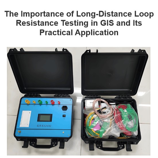
- Perform various product tests, such as resistance tests, and characteristic tests of current transformers, voltage transformers, circuit breakers, grounding switches, and disconnectors.
- Tighten the bolts at all flange joints outside the tank.
- Lay cables and perform wiring work.
- Apply anti - corrosion silicone grease in a timely manner at the flange joint positions during the product installation process.
- Equipment selection is crucial. Products with reliable quality that are suitable for the on - site environment must be chosen. For example, in plateau areas with large temperature differences between day and night, heaters need to be installed in the equipment to ensure the stability of the internal SF₆ gas. In coastal areas, anti - corrosion structures need to be considered, especially for the terminal plates of bushings, which are prone to moisture - induced corrosion, so a gluing process should be added.
- Equipment installation must be carried out strictly in accordance with the drawing requirements to avoid potential safety hazards.
- The connections between equipment must be carried out meticulously to meet cleanliness requirements and prevent potential discharge hazards.
- Inspect the appearance of the GIS equipment to confirm whether there are any damages or defects.
- Check the wiring of the control cabinet and its mechanisms, including electrical circuits, sensors, heaters, and drive systems, to ensure normal operation.
- Test the electrical operating performance of the GIS equipment to ensure it meets the functional requirements for electrical operation.
Technological Requirements during GIS Equipment Installation
- Set up a mobile maintenance box at the construction site to store disassembled components and maintenance tools.
- Equipment maintenance personnel should wear work clothes, safety helmets, and masks.
- The mating surfaces after equipment disassembly should be covered with dust covers immediately.
- Non - maintenance personnel should not frequently enter and exit the maintenance area.
- Special personnel should be responsible for checking the tools used for equipment maintenance to ensure nothing is left inside the equipment.
- Prevent dust, moisture, and fibers from entering and foreign objects from remaining inside the GIS equipment. Before replacing the adsorbent cover, a dedicated person should be assigned to do the final cleaning.
- The surface cleaning of the tank body and insulation parts is preferably carried out in a "suck - wipe" cycle.
The usage requirements for SF₆ gas recovery devices are as follows:
- The gas recovery device should be operated by personnel who have received special training and are familiar with the operation method.
- Before use, it should be confirmed that all parts of the recovery device are in good condition.
- During use, misoperation must be absolutely prevented to avoid contaminating the SF₆ gas or causing environmental pollution due to gas leakage.
- The recovery device should use dedicated hoses and be kept clean and dry.
- Lubricating greases for movable mechanical parts inside the GIS and for electrical contacts should be selected as required by the manufacturer.
- The layer of lubricating grease should not be too thick.
- When using vacuum silicone grease for all "O" - ring seals and flanges, avoid applying it to the inner side of the "O" - ring seal that comes into contact with the SF₆ gas.
The technological requirements for disassembly and assembly of sealing surfaces are as follows:
- Flange screws must be loosened diagonally along the circumferential direction.
- The sealing groove surface should not have scratches, and the sealing groove and flange plane should not rust.
- The grinding of damaged sealing groove surfaces should meet the manufacturer's requirements.
The technological requirements for replacing adsorbents are as follows:
- Adsorbents that are pre - treated and sealed - packaged at the factory can be used directly.
- Damaged or used bagged adsorbents must be dried before being installed.
- After the adsorbents are installed in the GIS, vacuum - pumping operations should be carried out immediately, and the time should be controlled within 30 minutes.
The technological requirements for vacuum - pumping are as follows:
- For disassembled gas chambers, pump to a vacuum of 40 Pa, continue pumping for 0.5 hours, stop the pump, and check the vacuum degree after 2 hours. If it is not more than 133 Pa, it is considered qualified. Fill with SF₆ gas to the rated pressure, and replenish the pressure in the depressurized gas chamber to the rated pressure.
- When detecting the vacuum degree, the McLeod gauge is strictly prohibited.
The technological requirements for filling SF₆ gas are as follows:
- When filling gas, first open the SF₆ gas cylinder and release a small amount of gas to prevent air from entering the GIS.
- Before use, the interface of the on - site gas - filling pipe should be cleaned, and after use, it should be properly stored and not placed on the ground to avoid introducing foreign objects during the gas - filling process.
- SF₆ gas cannot be directly filled into the gas chamber from the gas cylinder; it must be decompressed through a pressure - reducing valve.
- For SF₆ gas with sufficient micro - water content, the mass fraction of water should be less than 5×10⁻⁶, which is less than 40 μL/L when converted to volume ratio.
The technological requirements for local cover - type leak detection are as follows:
- The plastic cover (bag) should not have holes.
- All leakage points should be wrapped without omission.
- Detection personnel should be conscientious in detection, and the equipment and instruments should have good and reliable performance.
Implementing Safety Measures in GIS Equipment Installation

Strengthening Inspection and Maintenance of GIS Equipment after Installation
- Pay attention to safety protection measures. During operation, relevant regulations and standards must be strictly adhered to. Appropriate personal protective equipment should be worn to avoid accidents. Meanwhile, management of the on - site environment should also be strengthened to prevent dust, oil stains, etc. from entering the interior of electrical components and affecting their normal operation.
- Monitor changes in equipment status. In daily use, attention should be paid to changes in the equipment's status, such as temperature rise and abnormal current fluctuations, so that corresponding measures can be taken in a timely manner.
- Maintain records and feedback. For any problems or defects discovered, timely recording and reporting should be carried out, and solutions should be submitted to relevant departments for improvement and refinement. Based on actual conditions, formulating a reasonable inspection and maintenance plan to enhance the safety performance and service life of the equipment is one of the important means to achieve efficient and stable operation of GIS equipment.
- All connecting pipelines and connection components should be in good condition, clean, and free of oil stains. The connection between the pipeline and the product should be kept clean and can be wiped with lint - free paper dipped in alcohol.
- Before a pipeline that has been out of use for more than 10 days is reused, it needs to be purged and cleaned with high - purity nitrogen. After pipeline operations are completed, the connection heads should be sealed with plastic caps to prevent dust and foreign objects from entering.
- In case of a malfunction, immediately stop the operation, notify relevant personnel for handling, and promptly contact the maintenance department or the technical support team of the manufacturer to resolve the issue quickly. In case of emergencies such as fires or explosions, evacuate the site as soon as possible to avoid casualties.
- In case of equipment damage, immediately stop the machine and notify the relevant department for handling. Meanwhile, isolate the damaged part to prevent other components from being affected. If necessary, temporary repair methods can be adopted to ensure the normal operation of the equipment.
- Pay attention to basic safety issues, such as the wiring method of electrical circuits and the selection of power supply voltage. In actual operation, strictly comply with relevant safety regulations and standards to ensure that the device can operate normally without endangering the surrounding environment.

Professionalism builds strength. As an expert in the installation and operation of electrical equipment, I am proficient in the installation process and strictly adhere to standards. I skillfully master the operation essentials and can swiftly eliminate faults. With a heart that constantly explores new knowledge, I illuminate the path to the efficient operation of electrical equipment.


