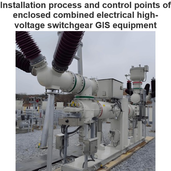
The 500 kV GIS system of Lianghekou Hydropower Station is composed of circuit breakers, disconnectors, earthing switches, bus - pipes, current transformers (CTs), potential transformers (PTs), arresters, etc. It has a total of 12 circuit - breaker bays, adopting an indoor structure and a "Z" - shaped layout, with 6 incoming lines and 2 outgoing lines, and using 4/3 and 3/2 wiring schemes. To meet the access of the Kela Photovoltaic project in the first - phase hydro - photovoltaic complementary project of Lianghekou Hydropower Station, a new outgoing - line bay (the third outgoing - line bay) has been added to Lianghekou Hydropower Station.
The 3/2 string where the No. 1 and No. 2 incoming lines are located has been expanded to a 4/3 string. The bay originally reserved for the access of Yagen - level - 1 Hydropower Station has been changed to a wind - and - photovoltaic access bay, and the equipment in the outgoing - line yard has been expanded accordingly. The interface between the expanded GIS equipment and the already - commissioned GIS equipment is at the 50132 and 50122 disconnectors and their associated gas compartments. Before the GIS expansion work starts, at the side of Unit 1, the power plant is responsible for the switching operations of the 50122 disconnector and the 50122 circuit breaker.
After completion, it notifies the project department that the half - voltage reduction operation on the gas compartment where the 50122 disconnector is located can begin. At the side of Unit 2, Lianghekou Power Plant is responsible for the switching operation of the 50132 disconnector and the shutdown operation of Unit 2. After completion, it notifies the installation unit that the half - voltage reduction operation on the gas compartment where the 50132 disconnector is located can start. After the expansion is completed, the installation unit is responsible for restoring the gas pressure in the 50132 and 50122 disconnectors and their associated gas compartments.
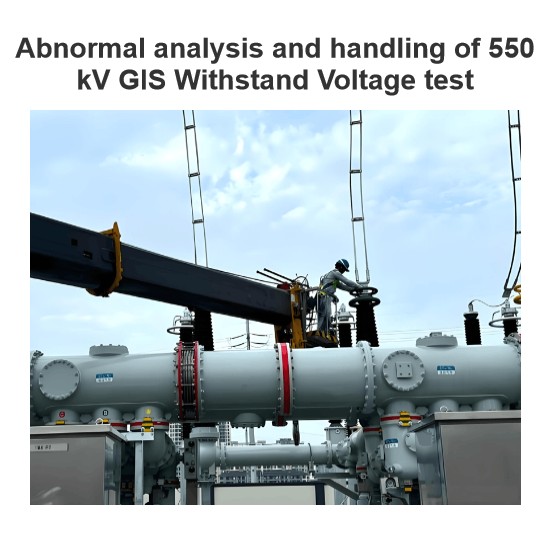
The construction period for the modification and expansion project of the third outgoing - line bay of Lianghekou Hydropower Station is only 30 days. Within these 30 days, the removal of existing bus - pipes and the installation and testing of new circuit breakers, CTs, and PTs need to be completed in the operating area. The construction period is tight, and the safety risks are high. Moreover, during the equipment installation process, lifting is restricted, and equipment installation cannot be completed through conventional lifting methods.
Analysis of Construction Difficulties
Installation of Newly - Added GIS Equipment
The interface between the newly - installed GIS equipment and the already - commissioned GIS equipment is at the 50132 and 50122 disconnectors and their associated gas compartments. When installing the new circuit breaker, the connecting bus - pipes and supports between 50132 and 50122 need to be removed, causing the CTs and PTs above the 50132 disconnector to be suspended, and temporary support is rather difficult. In addition, when installing the B - phase PT of the newly - added 50131 disconnector, it is blocked by the live busbar above, preventing the normal use of the GIS bridge crane for lifting, resulting in a relatively high installation difficulty.
Operations in the Operating Area
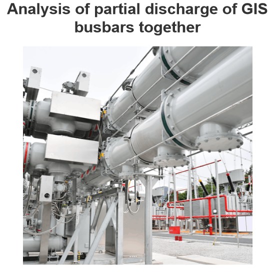
When the modification and expansion construction of the third outgoing - line bay is carried out, the equipment in the GIS room and the outgoing - line yard of Lianghekou Hydropower Station has been normally commissioned and is live. The modification and expansion construction requires the removal of some live and commissioned equipment and lifting operations in the vicinity, posing significant safety risks.
Construction Preparations
Preparation of a Full - scope Management List
Given the tight construction schedule and heavy workload of the third outgoing - line bay, and considering the construction is carried out in the operating area of the power plant, in order to ensure the smooth progress of the construction, the owner, supervisor, power plant, equipment manufacturer, and other parties jointly discuss and prepare a full - scope management list, and require all parties to fulfill their relevant responsibilities in strict accordance with the requirements of the list. The full - scope list is divided into the following six sections:
Power Outage Plan
All parties discuss and list the tasks that require applications to the power grid and dispatching, such as power grid outages and grid - related tests during the construction process. The installation unit applies to the power plant one week in advance, and the production department of the power plant applies to the dispatching.The power outage plan clearly defines the name of the main equipment to be powered off, the start and end times of the power outage, the main work content, and the required state of the powered - off equipment.
Construction and Commissioning Plan
The installation unit refines the construction and commissioning progress plan according to the power outage plan and the total construction period, requiring refinement to each process and clarifying the start and end times of each process.The installation unit determines the human resources invested in each process according to the construction and commissioning plan, and reasonably coordinates human resources.A daily afternoon meeting is held to correct deviations in the implementation of the construction plan, ensuring that tasks are completed on the same day.
Ticket - issuing List and Plan
To ensure the normal operation in the operating area, all parties jointly prepare a ticket - issuing list and plan. After the ticket - issuing list is completed, it is confirmed by the operation department of the owner's power plant. The operation department familiarizes itself with and prepares operation tickets in advance. The installation unit can only start the operation after obtaining tickets from the operation department of the power plant according to the ticket - issuing list. When issuing tickets, the contact person of the power plant is included in the work team members.The ticket - issuing list clearly defines the ticket - issuing name, operation content, person - in - charge of ticket - issuing work and contact information, operation time, and the contact person for ticket - issuing in the power plant.
List of Installation and Commissioning Schemes
Since the reconstruction and expansion involve the live connection of some secondary cables to the operating system of the power plant, which requires the operation of the maintenance department of the power plant, all parties agree that the maintenance department of the power plant prepares a cooperation scheme for the reconstruction and expansion of the third bay, and the installation unit prepares construction, commissioning, and testing schemes for the reconstruction and expansion.The list clearly defines the scheme name, responsible department, initial draft completion time, and final draft completion time.
Plan for the Entry of Personnel and Equipment
The installation unit lists the specific entry times of various types of workers, regular testers, high - voltage testers, mobile cranes, forklifts, trucks, and other personnel and equipment, and clarifies the responsible persons. The supervisor and the owner conduct assessments according to the schedule to urge the installation unit to ensure that personnel and equipment enter the site on time and that all resources are adequately prepared.
Plan for the Supply of Materials and Equipment
The installation unit lists the entry plan for equipment and materials supplied by Party B, and the owner lists the entry plan for equipment and materials supplied by Party A. All parties follow up and implement according to the entry plans of equipment and materials to ensure that the equipment and materials arrive on time.The plan categorically lists the equipment name, supply time, responsible person, manufacturer, and other information.
Technical Preparations
- Confirm with the power plant that the switching operations of GIS equipment have been completed, safety measures are in place, and construction conditions are met.
- Measurement and Layout: Based on the GIS installation layout diagram and combined with the installation elevation of the outlet bushing, review the elevation coordinate points for GIS equipment installation, measure, mark, and record the installation positions.
- Workers must change into work shoes and wear purification suits when entering the installation area. Work shoes and purification suits are not allowed to be worn outside the installation area. Other personnel should wear shoe covers when entering the installation area.
- Organize all construction workers to understand the layout characteristics of the equipment in the entire expanded bay and get familiar with the installation process and process requirements, based on relevant drawings and manufacturer's materials.
- Invite the manufacturer's and designer's on - site technicians and the supervision engineer to conduct a technical disclosure for all construction workers, so as to understand the design intent and the manufacturing plant's process characteristics, and correctly master the usage methods of professional tools.
- Prepare all kinds of records, inspection forms, and process cards required during the installation and commissioning processes.
Isolation between Construction Area and Operating Area
Before equipment installation, use retractable fences to reasonably plan the construction site, demarcating the construction area, operating area, isolation area (the side against the mountain for the main transformer incoming line of Unit 1, 5011 circuit breaker, and 5012 circuit breaker), equipment and material storage area, construction passage, and operating passage. For the secondary switchboards below the outlet branch busbars in the construction area, adopt hard isolation protection. Use scaffolding pipes to erect a protective shed and lay wooden boards on the top.
Inspection of Arrived Equipment and Materials
The following items are mainly inspected during the arrival acceptance of GIS equipment:
- Before unpacking, check whether the packaging is damaged and whether there is any collision, damage, or loss during transportation.
- Check the integrity and correctness of the delivered equipment according to the order and delivery documents.
- Check whether the paint, anti - rust layer, color, and quality on the equipment surface meet the requirements.
- Check whether the text and data on the nameplate are correct.
- Carefully check against the packing list whether the product accessories, spare parts, installation supplies, and special tools are complete, and whether there are any signs of damage, deformation, or rust.
- Check whether the bushings have any deformation, moisture, cracks, or defects.
- Check whether the factory certificates, relevant drawings, materials, and documents are complete.
- Check whether the value of the three - dimensional anti - tampering instrument exceeds 3 g.
Equipment Installation
Gas Recovery and Pressure Reduction
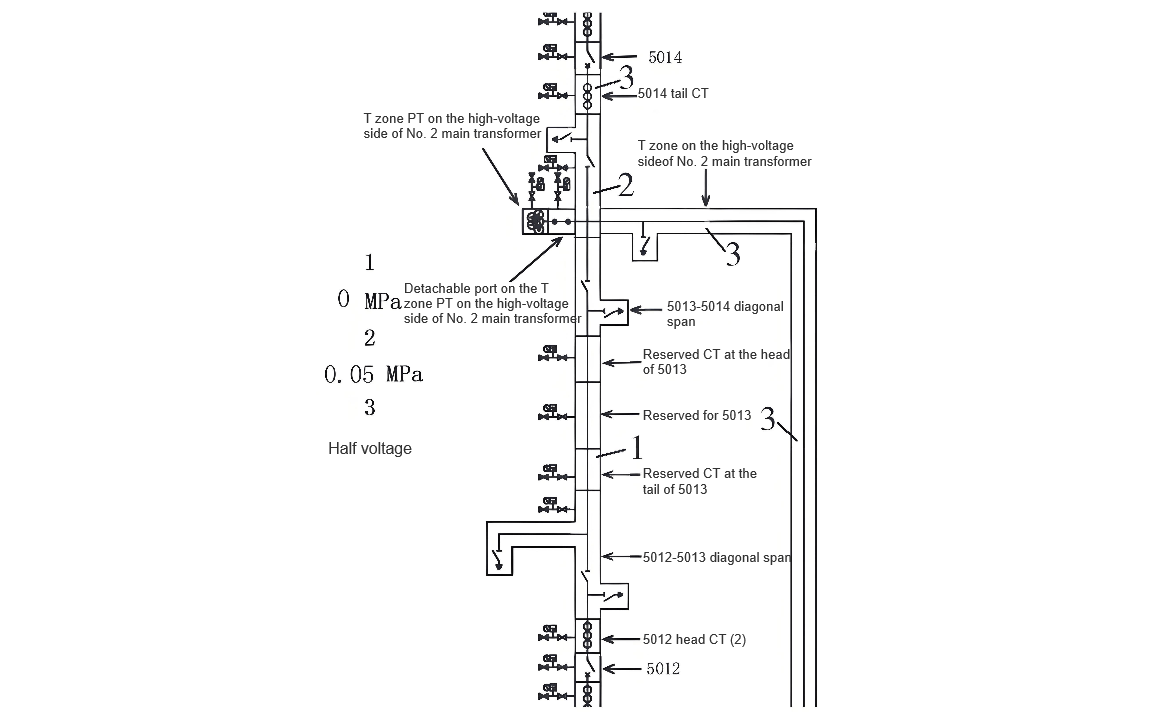
Before equipment installation, reduce the pressure to half at the detachable break points of the 5014 terminal CT, the high - voltage side T - zone PT of the No. 2 main transformer, the high - voltage side T - zone of the No. 2 main transformer, and the 5012 initial CT, as well as the high - voltage side T - zone PT of the No. 2 main transformer (see Part 3 in the figure for details); recover the gas from the 5013 - 5014 diagonal span to the 5012 initial CT (see Part 1 in the figure for details); retain a slight positive pressure of 0.05 MPa during gas recovery in the gas chamber from the 5014 terminal CT to the 5013 - 5014 diagonal span (see the colored block in Part 2 of the figure). The gas recovery and pressure reduction are shown in Figure 2.
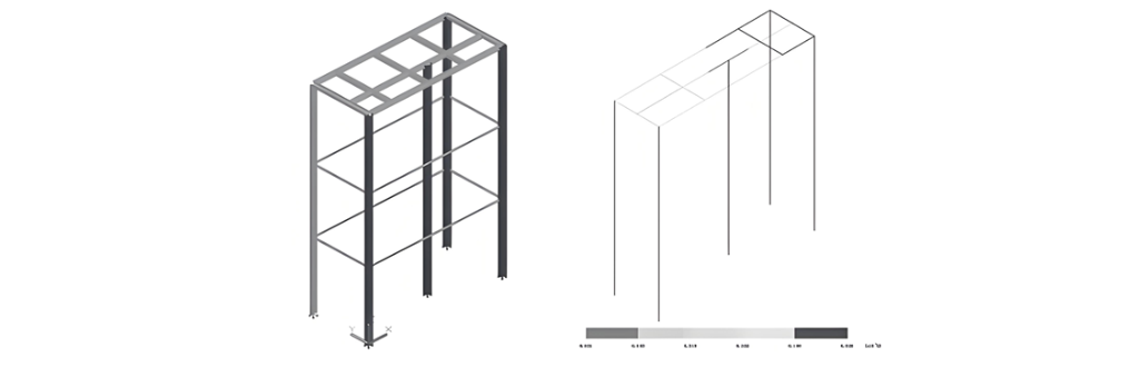
Disassembly and Support of Bus - pipes
After gas recovery and pressure reduction are completed, before the circuit breaker is positioned, first remove the maintenance platform, and then remove the "L" - shaped bus - pipe of 5013. When removing the "L" - shaped bus - pipe, use a gantry to hoist and fix the PT, CT, disconnector, 5013 - 5014 diagonal bus - pipe, and 5012 - 5013 diagonal bus - pipe in this area with the tooling.
Foundation Point - setting and Equipment Positioning
- According to the manufacturer's drawings, design drawings, and the installation status of existing equipment, use an ink line box to mark out and identify the (X, Y) center lines of the equipment. Measure and fix the relative positions of the equipment with a steel tape measure according to the center line of the B - phase of the incoming and outgoing lines; at the same time, mark the elevation points of the equipment to determine the installation elevation of the equipment.
- Install the equipment in place according to the design drawings, and review the centers and elevations of all equipment to ensure the correct installation positions.
- After the GIS room equipment is transported to the on - site hoisting hole in sequence, it is hoisted to the installation position inside the GIS room by a 10 - t single - girder crane. During hoisting, the "Ten No - Hoisting Rules" are strictly implemented. Each component must be test - hoisted for three times of lifting and lowering before hoisting. The hoisting area should try to avoid the operating area. The equipment must enter the site in strict accordance with the installation sequence to avoid the accumulation and congestion of equipment on - site, which may affect the installation progress. GIS equipment must be hoisted with the special lifting tools provided by the manufacturer, and the equipment should not be damaged during handling.
- When the equipment of a unit is initially positioned, first position the circuit breaker, and then position other equipment. Since the diagonal - spanning bus - pipe between 5013 and 5014 has not been removed, the 10 - t bridge crane in the GIS room [3 - 5] cannot directly hoist the circuit breaker into position. Therefore, in this installation, a manual hydraulic forklift is used to transport the circuit breaker to the installation position, and then the positioning adjustment is carried out. Ensure that the center and elevation of the circuit breaker meet the design requirements.
- Refer to the elevation of existing equipment during equipment installation. Before installation or connection, the equipment should be adjusted to be straight and level. Forcing, prying, or hard - aligning the equipment manually is strictly prohibited.
- Tighten all connecting bolts with a torque wrench according to the specified torque.
Installation of Voltage Transformers
- Since the B - phase voltage transformer behind the 5013 circuit breaker (weighing about 1 t and with an installation height of about 6 m) is installed directly below the B - phase of Bus Ⅱ, and Bus Ⅱ is in a live - operation state, the 10 - t bridge crane in the GIS room cannot directly hoist the voltage transformer into position. After consulting with multiple parties, it is decided to introduce an industrial forklift. The forklift has a rated load capacity of 1.5 t and a maximum lifting height of 7 m, which meets the on - site requirements and can move flexibly on - site.
- Before installation, check whether the internal pressure value of the transformer is the original inflation pressure and conduct routine tests.
- Clean the electrical contact surfaces on the sealing surface and the connecting flange with lint - free paper dipped in anhydrous alcohol.
- During the installation of the voltage transformer, adjust the verticality and levelness through the screws on the base to ensure a proper connection with the bus - connection surface and complete the flange connection.
- The conductor inside the detachable port at the lower end of the newly - added voltage transformer should be installed after the withstand voltage test is completed.
Conclusion
During the modification and expansion construction of the third bay of the 500 kV GIS at Lianghekou Hydropower Station, faced with unfavorable factors such as a tight construction schedule, construction in the operating area, and restricted lifting, through a series of measures including formulating a full - scope management list, manufacturing special tooling, and introducing industrial forklifts, the smooth progress of the modification and expansion construction of the third bay was ultimately ensured. This shortened the construction period, saved costs, and guaranteed safety and quality. It has set a precedent for in - depth cooperation between operations in the 500 kV GIS operating area and the power plant, and has certain reference and promoting significance for similar modification and expansion projects.