Synthetic current test for HVDC circuit breakers

Edwiin
11/22/2024

Circuit Description
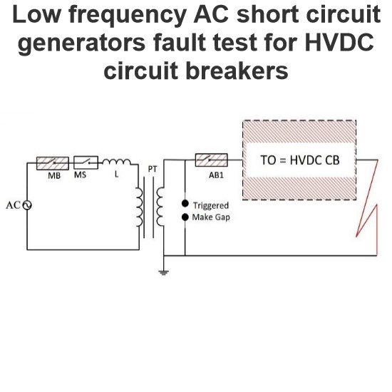
A 12-pulse rectifier is used as the current source to provide a DC test current, while a voltage oscillation circuit provides the recovery voltage after current switching. Auxiliary breakers and spark gaps are implemented in the circuit to connect these two sources to the test object at specific intervals. The specific implementation is as follows:

12-Pulse Rectifier: The rectifier is controlled to provide a DC test current to the test breaker (TB) through a smoothing reactor Ls and an auxiliary breaker (AB1) at a relatively low generator drive voltage.

Breaker Operation:

  • Initial Stage: Both the auxiliary breaker AB1 and the test breaker TB are closed, allowing the DC test current to flow through AB1 and TB to the test object.
  • Opening Stage: At a predetermined time, AB1 and TB are simultaneously opened, establishing a DC arc in the arc chutes of these breakers.

Spark Gap Triggering:

Spark Gap Action: The spark gap in the voltage circuit is ignited at the moment when the arc duration in TB reaches the expected value, providing the recovery voltage.

Current Bypass:

  • Bypass Stage: The auxiliary breaker AB2 closes, bypassing the DC current, which switches from the AB1 – TB branch to the AB2 bypass branch.
  • Clearing AB1: As the DC current switches from the AB1 – TB branch to the AB2 bypass branch, AB1 is cleared.

Recovery Voltage Application:

Injected Current: After AB1 is cleared, TB is only subjected to the injected current from the voltage circuit.

Clearing TB: When the injected current crosses zero, TB clears and is subjected to the transient recovery voltage and the subsequent DC voltage.

Rectifier Control:
Rectifier Blocking: The DC source rectifier is blocked upon receiving a stop signal, ceasing to provide the DC test current.

Diagram Explanation

  • 12-Pulse Rectifier: Provides a DC test current to the test breaker (TB) through a smoothing reactor Ls and an auxiliary breaker AB1.
  • Auxiliary Breaker AB1 and Test Breaker TB: Simultaneously open to establish a DC arc.
  • Spark Gap: Ignites when the arc duration in TB reaches the expected value, providing the recovery voltage.
  • Auxiliary Breaker AB2: Closes to bypass the DC current, clearing AB1.
  • Test Breaker TB: Clears when the injected current crosses zero, and is subjected to the transient recovery voltage and the subsequent DC voltage.
  • Rectifier: Is blocked upon receiving a stop signal, ceasing to provide the DC test current.

By following these steps, the circuit effectively tests the performance of the breaker under DC conditions, particularly during current switching and recovery voltage application.

Edwiin

HVDC valve hall earthing switches
Valve Hall OverviewThe valve hall is a specialized building housing the valves of a High-Voltage Direct Current (HVDC) static inverter. These valves are typically composed of thyristors, and in older plants, they may consist of mercury-arc rectifiers. The valve hall is a crucial component of the HVDC system, ensuring its safe and efficient operation.Grounding SystemThe grounding of valve hall components is ensured by highly customized grounding switches. For this purpose, two different types of
Edwiin
11/25/2024
Fault clearing currents curve in HVDC hybrid circuit breaker Simulink
Hybrid Circuit Breaker with IGBT Simulink Electronic InterruptionIn a hybrid circuit breaker with IGBT Simulink electronic interruption (as shown in the left figure), the fault current is diverted from the main path to the interrupter path by the IGBTs in path 1. Meanwhile, a local current zero-crossing is created by a set of IGBTs in path 2.In the right figure, the short-circuit fault current begins to flow through the circuit breaker at t1. Then, at t2 , the current is interrupted in path 1 (a
Edwiin
11/23/2024
Low frequency AC short circuit generators fault test for HVDC circuit breakers
Given the Circuit Breaker Operating Time, the Magnitude of the Driving Voltage, the Turn-On Angle, the Circuit Inductance, and the Generator Frequency Are Key Design Parameters for Achieving Sufficient di/dt and Adequate Energy Supply.After current interruption, the dielectric stress can be provided by a separate DC voltage source, although this presents some practical challenges. The capacitor remains charged throughout the energy absorption period, with its value equal to the TRV (Transient Re
Edwiin
11/20/2024
Filter Earthing Switch(FES) role in HVDC grids
High voltage ground switch definitionA high-voltage ground switch is a mechanical switching device used to connect high-voltage electrical equipment or lines to the ground to ensure safety during equipment overhaul or troubleshooting. It is usually installed next to high-voltage circuit breakers, isolation switches, transformers and other devices to ground high-voltage circuits quickly and reliably when needed.The role of the filter grounding switch in the HVDC network:The main function of the f
Edwiin
11/15/2024
Inquiry
Download
Experts Electrical is dedicated to serving the personnel in the global power industry.
Join Experts Electrical, not only can you discover power equipment and power knowledge, but also canhnd like - minded friends!