HVDC valve hall earthing switches

Edwiin
11/25/2024

Valve Hall Overview

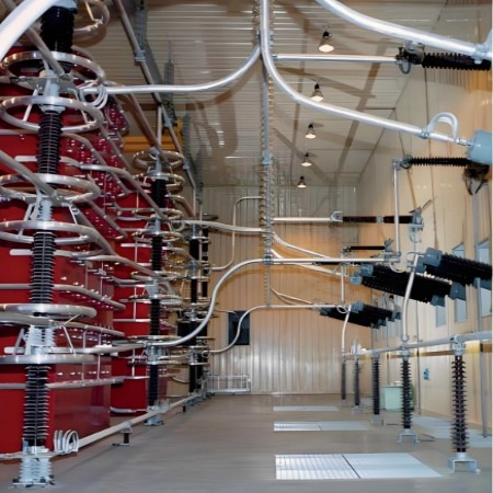
The valve hall is a specialized building housing the valves of a High-Voltage Direct Current (HVDC) static inverter. These valves are typically composed of thyristors, and in older plants, they may consist of mercury-arc rectifiers. The valve hall is a crucial component of the HVDC system, ensuring its safe and efficient operation.

Grounding System

The grounding of valve hall components is ensured by highly customized grounding switches. For this purpose, two different types of grounding switches are used:

  • Wall-Mounted Grounding Switches: Installed on walls, suitable for space-restricted environments.
  • Floor-Mounted Half-Pantograph Grounding Switches: Installed on the ground, suitable for situations requiring more operational space.

Maintenance Requirements

During maintenance, it is essential to insert grounding switches at key installation points. Since the space between transformers and rectifiers must be minimized, grounding switches must fit into limited spaces and adapt to the actual layout. Grounding switches are the most effective solution for grounding transformer AC bushings, DC busbars of both poles, or any required points in AC or DC circuits.

Functionality of Grounding Switches

Depending on their function, grounding switches can be equipped with supporting insulators. If disconnect functionality is required, the same design principles will provide equally effective solutions, especially when switching DC filters, which necessitate connecting and disconnecting residual currents.

Summary

Grounding switches play a critical role in the maintenance and safe operation of HVDC systems. They not only ensure proper grounding but also provide flexible disconnect capabilities to meet different operational needs. By being properly designed and installed, grounding switches can effectively protect the system from potential electrical risks, ensuring its reliability and safety.

Edwiin

Earthing Switches definition in high voltage conventional substations
Overview of Grounding SwitchesA grounding switch is a mechanical device specifically designed to safely connect a circuit to earth (ground). It is capable of withstanding fault currents for a certain period during short circuits or other abnormal conditions, while not carrying load current during normal operation. Therefore, grounding switches play a crucial role in power systems by ensuring the safety of personnel and equipment.Key FunctionsGrounding switches should be able to perform the follo
Edwiin
11/30/2024
Fault clearing currents curve in HVDC hybrid circuit breaker Simulink
Hybrid Circuit Breaker with IGBT Simulink Electronic InterruptionIn a hybrid circuit breaker with IGBT Simulink electronic interruption (as shown in the left figure), the fault current is diverted from the main path to the interrupter path by the IGBTs in path 1. Meanwhile, a local current zero-crossing is created by a set of IGBTs in path 2.In the right figure, the short-circuit fault current begins to flow through the circuit breaker at t1. Then, at t2 , the current is interrupted in path 1 (a
Edwiin
11/23/2024
Synthetic current test for HVDC circuit breakers
Circuit DescriptionA 12-pulse rectifier is used as the current source to provide a DC test current, while a voltage oscillation circuit provides the recovery voltage after current switching. Auxiliary breakers and spark gaps are implemented in the circuit to connect these two sources to the test object at specific intervals. The specific implementation is as follows:12-Pulse Rectifier: The rectifier is controlled to provide a DC test current to the test breaker (TB) through a smoothing reactor L
Edwiin
11/22/2024
Low frequency AC short circuit generators fault test for HVDC circuit breakers
Given the Circuit Breaker Operating Time, the Magnitude of the Driving Voltage, the Turn-On Angle, the Circuit Inductance, and the Generator Frequency Are Key Design Parameters for Achieving Sufficient di/dt and Adequate Energy Supply.After current interruption, the dielectric stress can be provided by a separate DC voltage source, although this presents some practical challenges. The capacitor remains charged throughout the energy absorption period, with its value equal to the TRV (Transient Re
Edwiin
11/20/2024
Inquiry
Download
Experts Electrical is dedicated to serving the personnel in the global power industry.
Join Experts Electrical, not only can you discover power equipment and power knowledge, but also canhnd like - minded friends!