Fault clearing currents curve in HVDC hybrid circuit breaker Simulink

Hybrid Circuit Breaker with IGBT Simulink Electronic Interruption
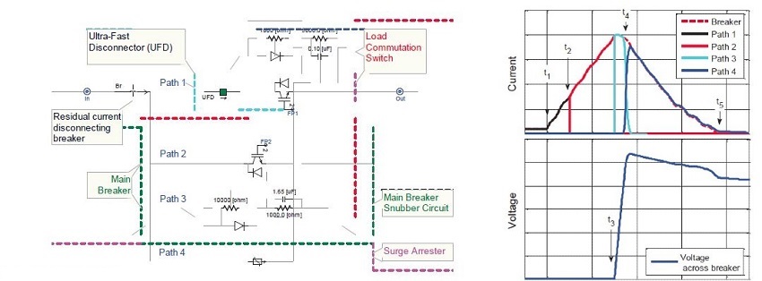
In a hybrid circuit breaker with IGBT Simulink electronic interruption (as shown in the left figure), the fault current is diverted from the main path to the interrupter path by the IGBTs in path 1. Meanwhile, a local current zero-crossing is created by a set of IGBTs in path 2.
In the right figure, the short-circuit fault current begins to flow through the circuit breaker at t1. Then, at t2 , the current is interrupted in path 1 (as shown in the left figure), and the fault current is diverted to path 2. Next, at t3 , the current is interrupted in path 2 and diverted to path 3. The high impedance of path 3 causes a sharp rise in voltage until the surge protector limits this voltage at t4. This voltage is known as the Transient Interruption Voltage (TIV).
It is important to recognize that from t4 onward, the system begins to recover, even though the current at the fault location has not yet been completely interrupted. The faulty section is effectively isolated from the normal part of the system. From this point, the voltage (higher than the rated system voltage) steadily reduces the current to zero, while the system's inductive energy dissipates in the surge protector in path 4.
Diagram Explanation
- At t1 : The short-circuit fault current begins to flow through the circuit breaker.
- At t2 : The IGBTs in path 1 act to divert the fault current to path 2.
- At t3 : The IGBTs in path 2 act to divert the fault current to path 3.
- At t4 : The high impedance of path 3 causes a sharp rise in voltage, and the surge protector acts to limit this voltage, forming the Transient Interruption Voltage (TIV).
System Recovery Process
- Fault Isolation: From t4 onward, the faulty section is effectively isolated from the normal part of the system.
- Voltage Recovery: The voltage, which is higher than the rated system voltage, gradually reduces the current to zero.
- Energy Dissipation: The system's inductive energy dissipates in the surge protector in path 4, ensuring the system returns to normal operation.
By this method, the hybrid circuit breaker can quickly and effectively handle short-circuit faults, protecting the power system from damage.


