Low frequency AC short circuit generators fault test for HVDC circuit breakers

Given the Circuit Breaker Operating Time, the Magnitude of the Driving Voltage, the Turn-On Angle, the Circuit Inductance, and the Generator Frequency Are Key Design Parameters for Achieving Sufficient di/dt and Adequate Energy Supply.
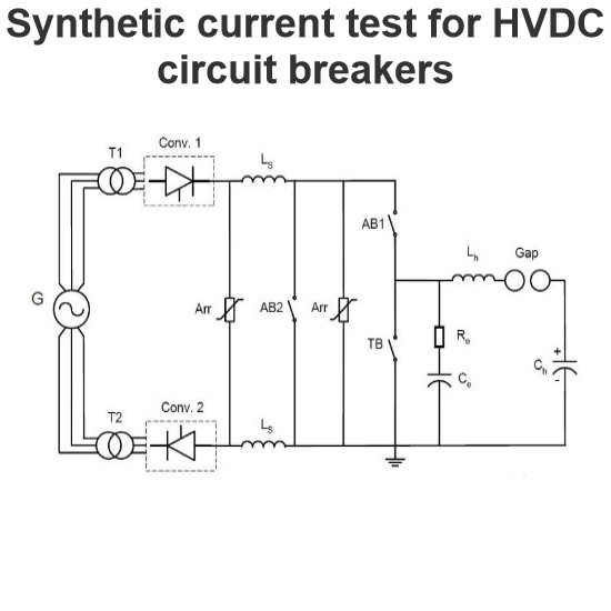
After current interruption, the dielectric stress can be provided by a separate DC voltage source, although this presents some practical challenges. The capacitor remains charged throughout the energy absorption period, with its value equal to the TRV (Transient Recovery Voltage) of the circuit breaker. This can be deployed to provide dielectric stress after interruption.
The test circuit diagram shown is equivalent to the test object (HVDC CB). It uses 3 short-circuit generators and 3 step-up transformers. The main breaker (MB) must close the primary current on the generator side within a single loop. The turn-on switch (MS) needs to be precisely set to the fault current to create "DC-like" conditions within the fault suppression time of the DC CB. AC circuit breakers (ACB1) and triggered turn-on gaps are added to the circuit for current isolation in the power circuit, to prevent subsequent additions of DC power and overcurrent protection.
Detailed Explanation
-
Design Parameters:
- Circuit Breaker Operating Time: The time it takes for the circuit breaker to operate is critical for ensuring proper current interruption.
- Magnitude of Driving Voltage: The voltage level driving the circuit must be sufficient to achieve the desired di/dt (rate of change of current).
- Turn-On Angle: The angle at which the circuit breaker is turned on affects the initial current and voltage conditions.
- Circuit Inductance: The inductance of the circuit influences the rate of current rise and fall.
- Generator Frequency: The frequency of the generator impacts the timing and synchronization of the circuit breaker operations.
-
Dielectric Stress After Current Interruption:
- Separate DC Voltage Source: Providing dielectric stress after current interruption using a separate DC voltage source is a viable approach, but it introduces practical challenges.
- Charged Capacitor: The capacitor remains charged during the energy absorption period, maintaining a voltage equal to the TRV of the circuit breaker. This ensures continuous dielectric stress after the interruption.
-
Test Circuit Configuration:
- Short-Circuit Generators and Step-Up Transformers: The test setup includes 3 short-circuit generators and 3 step-up transformers to simulate realistic fault conditions.
- Main Breaker (MB): The main breaker closes the primary current on the generator side within a single loop, ensuring a controlled environment for testing.
- Turn-On Switch (MS): The turn-on switch must be precisely set to the fault current to create "DC-like" conditions within the fault suppression time of the DC CB.
- AC Circuit Breakers (ACB1) and Triggered Turn-On Gaps: These components are added to the circuit for current isolation, preventing the addition of DC power and providing overcurrent protection.
By carefully considering these design parameters and configuring the test circuit appropriately, it is possible to effectively test and validate the performance of HVDC circuit breakers under various operating conditions.