Filter Earthing Switch(FES) role in HVDC grids
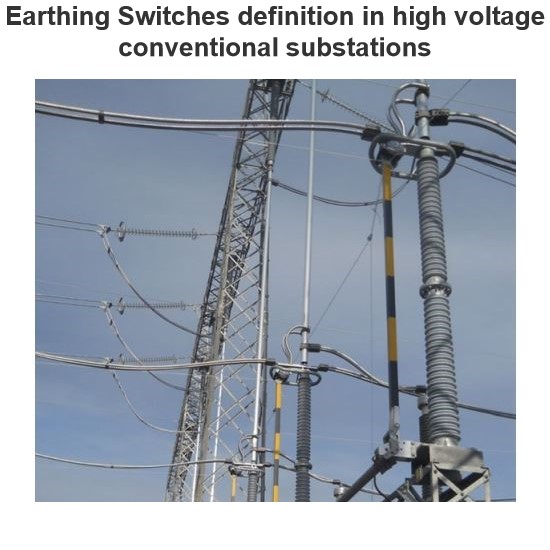
High voltage ground switch definition
A high-voltage ground switch is a mechanical switching device used to connect high-voltage electrical equipment or lines to the ground to ensure safety during equipment overhaul or troubleshooting. It is usually installed next to high-voltage circuit breakers, isolation switches, transformers and other devices to ground high-voltage circuits quickly and reliably when needed.
The role of the filter grounding switch in the HVDC network:
The main function of the filter grounding switch is to ground the tail end of the passive AC filter (ACF) to ensure that the ACF can operate normally when the active filter (APF) is out of operation. This design can solve the problem of 5th and 7th harmonics in the case of the power grid with large harmonics and poor harmonic impedance conditions of the system, thereby improving the capacity and operation safety of the filter equipment.
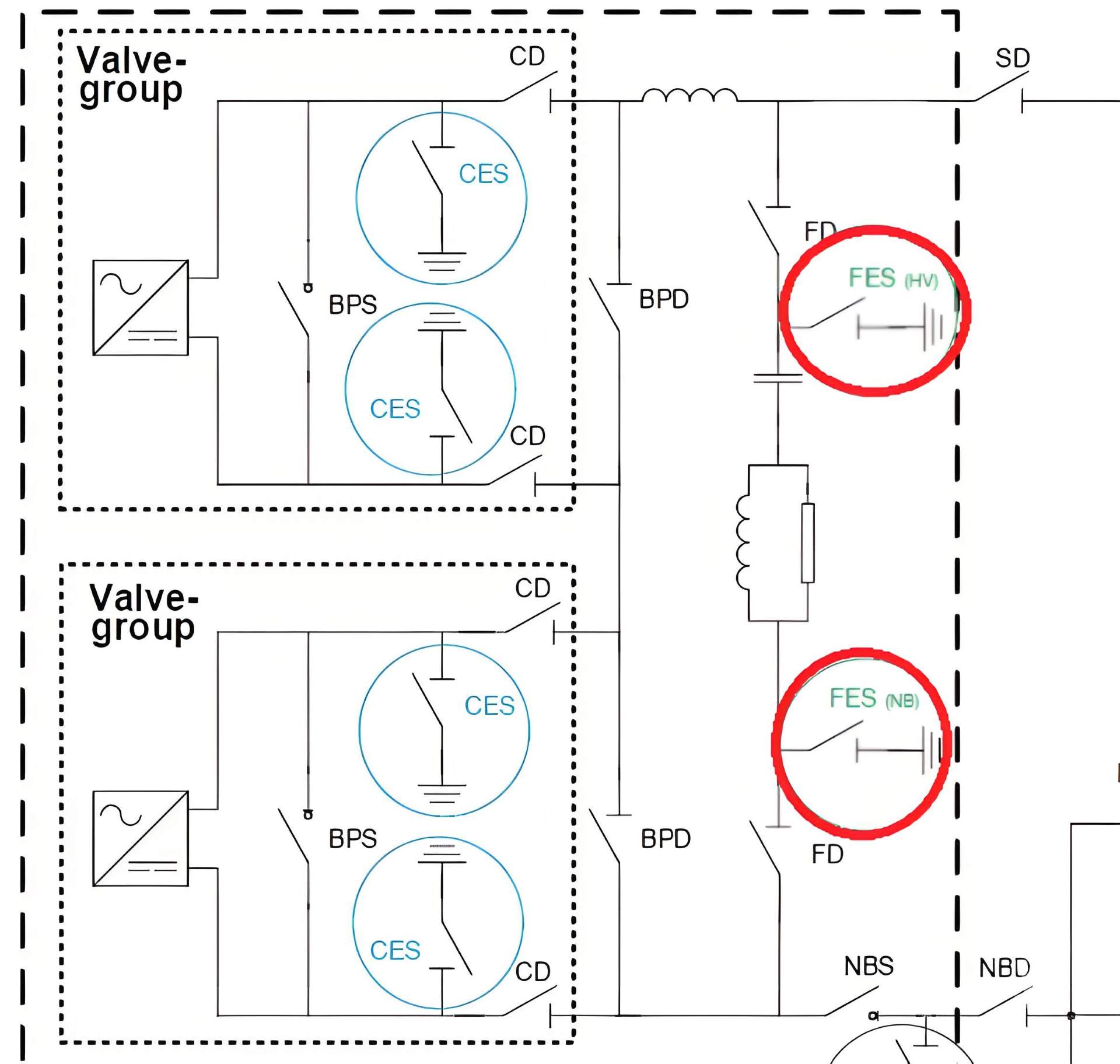
The position of the filter ground switch is shown in the red circle in Figure 1:
In high voltage direct current (HVDC) systems, the order of operation of the filter ground switch is crucial to ensure the safe and stable operation of the system. The following are the operating steps and precautions for the filter grounding switch in normal operation:
Normal operating condition
Grounding Switch status: In normal operation, the filter grounding switch (GS) is turned on to ensure that the filter can work normally.
Operation procedure
Preparatory work
- Receive operational instructions: Ensure that clear operational instructions are received from the dispatch center or other authorized personnel.
- Check information: Check the number of the filter and grounding switch to ensure that there are no misoperations.
Turn-off filter
- Disconnect the Circuit Breaker: First disconnect the circuit breaker (CB) connecting the filter to the system to ensure that the filter is completely isolated from the system.
- Disconnect the isolation switch FD (HV) : After the circuit breaker is disconnected, disconnect the Filter from the HV Pole Side Filter Disconnector (FD (HV)) to further ensure the isolation of the filter from the system.
Check residual charge
- Measure the residual voltage: Using the appropriate voltage detection equipment, measure the residual voltage of the filter capacitor bank to ensure that the voltage has dropped to a safe level.
- Record measurement results: Record measurement results to ensure complete operation records.
Close filter ground switch GS (HV)
- Ensure isolation switch status: Ensure that the isolation switch FD (HV) is off and the isolation switch FD (NB) (NB Side Filter Disconnector) is on.
- Manual or electric operation: According to the operation manual, manually or electrically close the filter ground switch GS (HV).
- Check the grounding status: Check the status indicator of the grounding switch to ensure that the grounding switch is properly closed.
Close filter ground switch GS (NB)
- Disconnect the isolation switch FD (NB) : After closing the ground switch GS (HV), disconnect the isolation switch FD (NB).
- Turn on ground switch GS (NB) : After ensuring that the isolation switches FD (HV) and FD (NB) are both off, turn on the filter ground switch GS (NB).
- Check the grounding status: Check the status indicator of the grounding switch to ensure that the grounding switch is properly closed.
Recheck
Measure the voltage again: After closing the ground switch GS (NB), measure the voltage of the filter capacitor bank again to ensure that the voltage has been fully released to zero.
Record measurement results: Record the results of the re-measurement to ensure that the operation record is complete.
Complete operation
- Confirm safety: Ensure that the filter is reliably grounded and the operating area is safe.
- Report completion: Report the completion of the operation to the dispatch center or other authorized personnel, and record the operation time and result.
Interlocking mechanism
- Interlocking requirements: Ensure that the disconnecting switch FD (HV) must be off and the disconnecting switch FD (NB) must be off before the filter ground switch GS (HV) is turned on.
- Secondary confirmation: Make sure that both the isolation switches FD (HV) and FD (NB) are off before closing the filter ground switch GS (NB).
- Automatic interlocking: The system should have automatic interlocking function to prevent safety accidents caused by misoperation.
Technical requirement
Breaking capacity
No breaking capability required: The Filter Earthing Switch (FES) does not require breaking capability. This means that it does not need to have the ability to disconnect the circuit under load.
Discharge capacity
Discharge filter: The filter grounding switch must be able to reliably ground the partial discharge filter connected to the neutral line via the isolation switch FD (NB). This ensures that the residual charge in the filter capacitor bank is fully released when maintenance or overhaul is performed.
Switching capacity
No need for connection capability: Ground switch FES does not require connection capability. In most cases, conventional ground switches can be used to meet this need.
Maintenance
Maintenance after the filter is disconnected: The maintenance of the filter ground switch FES can be carried out after the filter is disconnected to ensure the safety of the operator.
Pressure resistance
Open contact and DC voltage resistance to ground: Open contact and DC voltage resistance to ground should be the same as other devices connected to the pole and neutral lines. This ensures the reliability and safety of the filter grounding switch in high voltage environments.
Uptime characteristic
- Low leakage current: Under normal circumstances, the filter grounding switch has no normal current passing through except for a portion of very low leakage current.
- Turn-on capability: The filter ground switch has the turn-on capability as the filter trap charging current in the HVDC network. This ensures that the filter can be reliably connected to the ground when needed.
Standards and grades
IEC standards: According to IEC standards, the grade of the filter ground switch is mostly E0. The E0 level indicates that the switch does not encounter the need to break current during normal operation, and only needs to have basic grounding and discharge functions.
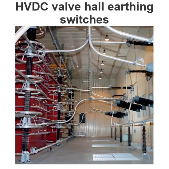
We can see a kind of HVDC earthing switch in figure No:2 as below made by Coelme-Egic company:
