HVDC hybrid circuit breaker topology

Edwiin
11/29/2024

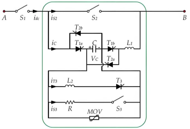
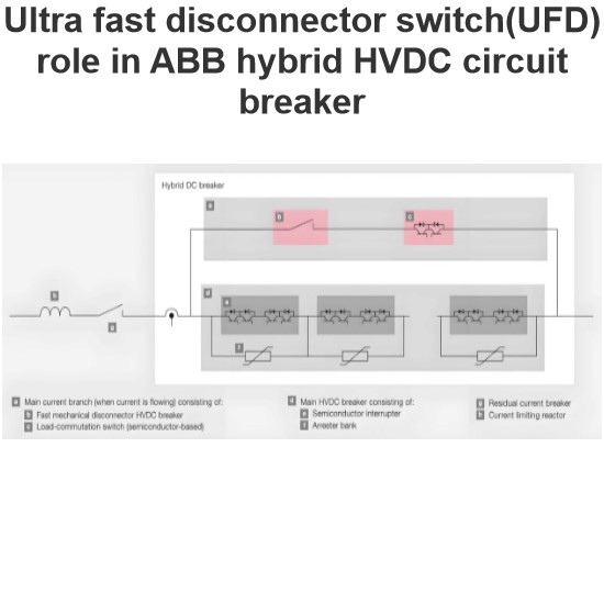
A high-voltage DC hybrid circuit breaker is a sophisticated and efficient device designed to quickly and reliably interrupt fault currents in high-voltage DC circuits. The breaker primarily consists of three components: the main branch, the energy absorption branch, and the auxiliary branch.

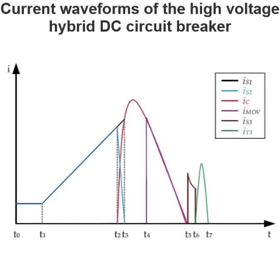
The main branch features a fast mechanical switch (S2), which rapidly disconnects the main circuit upon detection of a fault, preventing further flow of fault current. This rapid response capability is crucial for preventing system damage.

The auxiliary branch is more intricate, comprising a capacitor (C), a resistor (R), a fast mechanical switch (S3), and two inductors (L1 and L2). Additionally, it includes five thyristors (T1a, T1b, T2a, T2b, and T3) that play key roles in controlling the circuit. Thyristors T1a, T1b, T2a, and T2b are used to interrupt bidirectional fault currents, ensuring effective disconnection regardless of the direction of the current. Thyristor T3 is responsible for reversing the polarity of the capacitor voltage when necessary, providing essential conditions for subsequent operations.

The energy absorption branch consists of a series and parallel arrangement of metal oxide varistors (MOVs). These components effectively absorb and dissipate excess energy generated by fault currents, while also protecting the capacitor from overvoltage. This feature is particularly important for maintaining system stability and safety.

To achieve complete isolation of the entire DC circuit, a residual DC current circuit breaker (S1) is also included. When it is necessary to completely disconnect the circuit from the power source, this breaker comes into play, ensuring the safety of maintenance and repair work.

Notably, mechanical switches S1, S2, and S3 all utilize vacuum interrupter technology, which not only enhances the speed and efficiency of switching operations but also effectively extinguishes arcs, reducing electrical wear and extending the lifespan of the equipment. In summary, the high-voltage DC hybrid circuit breaker achieves safe and efficient management of high-voltage DC circuits through its meticulously designed multi-branch structure.

Edwiin

Current waveforms of the high voltage hybrid DC circuit breaker
The operation of a hybrid circuit breaker is divided into eight intervals, corresponding to four operational modes. These intervals and modes are as follows:Normal Mode (t0~t2):During this interval, power is transmitted seamlessly between the two sides of the circuit breaker.Breaking Mode (t2~t5):This mode is used to interrupt fault currents. The circuit breaker rapidly disconnects the faulty section to prevent further damage.Discharge Mode (t5~t6):In this interval, the voltage across the capaci
Edwiin
11/28/2024
High voltage HVDC switches in grid
The Typical Single-Line Diagram of an HVDC Transmission Scheme Using DC Side SwitchgearThe typical single-line diagram shown in the figure illustrates an HVDC transmission scheme utilizing DC side switchgear. The following switches can be identified from the diagram:NBGS – Neutral Bus Grounding Switch:This switch is typically in the open position. When closed, it firmly connects the converter's neutral line to the station ground pad. If the converter can operate in bipolar mode with balanc
Edwiin
11/27/2024
Ultra fast disconnector switch(UFD) role in ABB hybrid HVDC circuit breaker
Hybrid DC Circuit Breaker SolutionThe hybrid DC circuit breaker solution combines the excellent switching capabilities of power electronic devices (such as IGBTs) with the low-loss characteristics of mechanical switchgear. This design ensures that, unless interruption is needed, current does not flow through the semiconductors in the main circuit breaker. This is achieved through a mechanical bypass path, which consists of a super-fast disconnector (UFD) and an auxiliary commutation switch conne
Edwiin
11/26/2024
HVDC valve hall earthing switches
Valve Hall OverviewThe valve hall is a specialized building housing the valves of a High-Voltage Direct Current (HVDC) static inverter. These valves are typically composed of thyristors, and in older plants, they may consist of mercury-arc rectifiers. The valve hall is a crucial component of the HVDC system, ensuring its safe and efficient operation.Grounding SystemThe grounding of valve hall components is ensured by highly customized grounding switches. For this purpose, two different types of
Edwiin
11/25/2024
Inquiry
Download
Experts Electrical is dedicated to serving the personnel in the global power industry.
Join Experts Electrical, not only can you discover power equipment and power knowledge, but also canhnd like - minded friends!