High voltage HVDC switches in grid

Edwiin
11/27/2024
The Typical Single-Line Diagram of an HVDC Transmission Scheme Using DC Side Switchgear
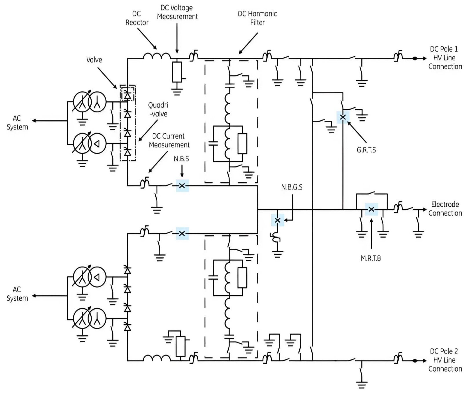
The typical single-line diagram shown in the figure illustrates an HVDC transmission scheme utilizing DC side switchgear. The following switches can be identified from the diagram:
- NBGS – Neutral Bus Grounding Switch:This switch is typically in the open position. When closed, it firmly connects the converter's neutral line to the station ground pad. If the converter can operate in bipolar mode with balanced current between the poles, resulting in very low direct current to ground, this switch can usually remain closed.
- NBS – Neutral Bus Switch:The NBS is connected in series with the neutral connection of each pole. If a ground fault occurs in one pole, that pole will be blocked, thus protecting the system from the fault.
- GRTS – Ground Return Transfer Switch:The connection between the HVDC conductor and the neutral point includes a high-voltage circuit breaker and the GRTS. The GRTS is used as part of the switching operation to configure the HVDC system for either ground return monopolar or metal return monopolar modes.
- MRTB – Metal Return Transfer Breaker:The MRTB is used in conjunction with the GRTS to transfer the DC load current between the ground return mode (ground loop) and the parallel mode (unused high-voltage conductor).
Explanation
- NBGS: During normal operation, the NBGS is typically kept open to prevent unnecessary ground currents. However, in specific situations, such as when operating in bipolar mode with well-balanced currents between the poles, the NBGS can be closed to provide additional grounding protection.
- NBS: The NBS is used to protect the system from ground faults. When a fault occurs in one pole, the NBS can quickly disconnect the neutral connection of that pole, preventing the fault from spreading.
GRTS: The GRTS is a critical switching device used to switch between different operating modes of the HVDC system. It works in conjunction with the high-voltage circuit breaker to ensure stability and safety during the switching process. - MRTB: The MRTB is used to switch the DC load current between ground return mode and metal return mode. This switching operation helps optimize the system's operational efficiency and reliability.
By coordinating the operation of these switchgear devices, the HVDC system can flexibly switch between different operating modes, ensuring safe, reliable, and efficient system operation.
Topics
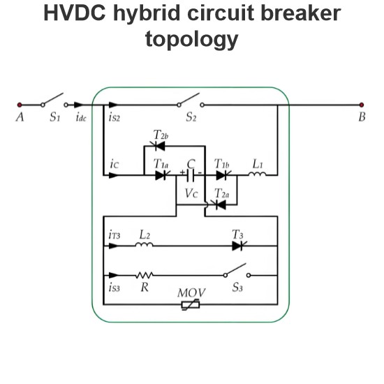
HVDC hybrid circuit breaker topology
A high-voltage DC hybrid circuit breaker is a sophisticated and efficient device designed to quickly and reliably interrupt fault currents in high-voltage DC circuits. The breaker primarily consists of three components: the main branch, the energy absorption branch, and the auxiliary branch.The main branch features a fast mechanical switch (S2), which rapidly disconnects the main circuit upon detection of a fault, preventing further flow of fault current. This rapid response capability is crucia
Edwiin
11/29/2024
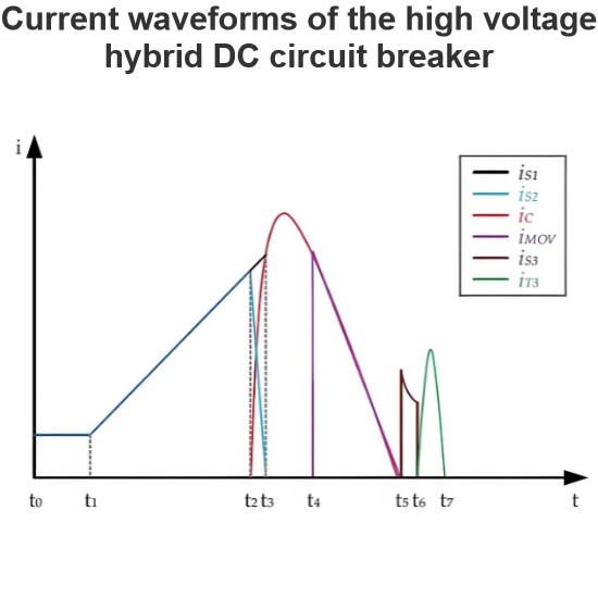
Current waveforms of the high voltage hybrid DC circuit breaker
The operation of a hybrid circuit breaker is divided into eight intervals, corresponding to four operational modes. These intervals and modes are as follows:Normal Mode (t0~t2):During this interval, power is transmitted seamlessly between the two sides of the circuit breaker.Breaking Mode (t2~t5):This mode is used to interrupt fault currents. The circuit breaker rapidly disconnects the faulty section to prevent further damage.Discharge Mode (t5~t6):In this interval, the voltage across the capaci
Edwiin
11/28/2024
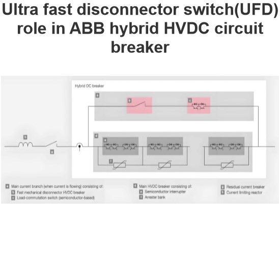
Ultra fast disconnector switch(UFD) role in ABB hybrid HVDC circuit breaker
Hybrid DC Circuit Breaker SolutionThe hybrid DC circuit breaker solution combines the excellent switching capabilities of power electronic devices (such as IGBTs) with the low-loss characteristics of mechanical switchgear. This design ensures that, unless interruption is needed, current does not flow through the semiconductors in the main circuit breaker. This is achieved through a mechanical bypass path, which consists of a super-fast disconnector (UFD) and an auxiliary commutation switch conne
Edwiin
11/26/2024
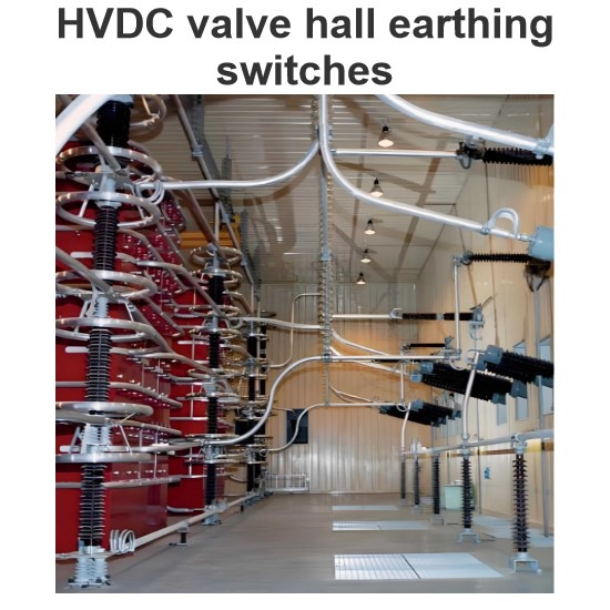
HVDC valve hall earthing switches
Valve Hall OverviewThe valve hall is a specialized building housing the valves of a High-Voltage Direct Current (HVDC) static inverter. These valves are typically composed of thyristors, and in older plants, they may consist of mercury-arc rectifiers. The valve hall is a crucial component of the HVDC system, ensuring its safe and efficient operation.Grounding SystemThe grounding of valve hall components is ensured by highly customized grounding switches. For this purpose, two different types of
Edwiin
11/25/2024


