Ultra fast disconnector switch(UFD) role in ABB hybrid HVDC circuit breaker

Hybrid DC Circuit Breaker Solution
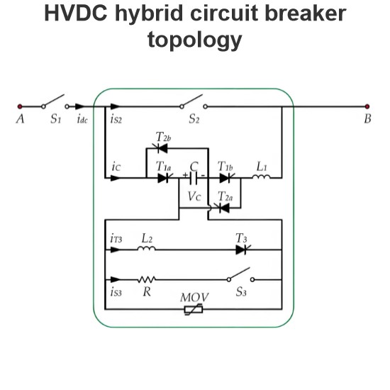
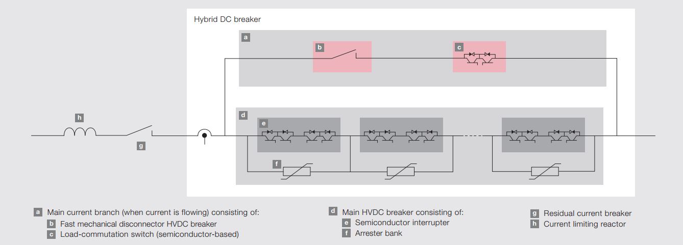
The hybrid DC circuit breaker solution combines the excellent switching capabilities of power electronic devices (such as IGBTs) with the low-loss characteristics of mechanical switchgear. This design ensures that, unless interruption is needed, current does not flow through the semiconductors in the main circuit breaker. This is achieved through a mechanical bypass path, which consists of a super-fast disconnector (UFD) and an auxiliary commutation switch connected in series, as shown in the figure.
Working Principle
Normal Operation:
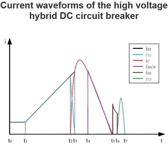
During normal operation, current flows through the mechanical bypass path, with the UFD and the auxiliary commutation switch both in the closed position. Therefore, current does not flow through the semiconductors in the main circuit breaker, reducing losses.
Fault Detection and Interruption:
When a fault is detected, the auxiliary commutation switch rapidly switches the current from the bypass path to the parallel main circuit breaker. This process ensures that the UFD can separate its contacts under almost zero current stress, thus avoiding arc formation and overheating.
Role of UFD:
- Complete Dielectric Insulation: The UFD must provide complete dielectric insulation between its contacts after the main circuit breaker has operated (i.e., after it has interrupted the current) to prevent re-conduction of current.
- Maximum Rated Current: The UFD must be able to withstand the system's maximum rated current to ensure reliable operation under all conditions.
Rapid Response: In the event of unexpected failures in system subcomponents, the UFD must be able to immediately perform the closing operation to protect the entire system from damage.
Diagram Explanation
In the diagram, the super-fast disconnector switch is labeled as item b. The layout of the entire system is as follows:
- Mechanical Bypass Path: Consists of the UFD and the auxiliary commutation switch connected in series.
- Main Circuit Breaker: Contains power electronic devices (such as IGBTs) for quickly interrupting current during faults.
- Auxiliary Commutation Switch: Rapidly switches the current from the bypass path to the main circuit breaker upon fault detection.
Conclusion
The hybrid DC circuit breaker solution achieves efficient and reliable current interruption by combining the fast-switching characteristics of power electronic devices with the low-loss characteristics of mechanical switches. The key role of the UFD is to ensure rapid and safe current interruption and to provide the necessary dielectric insulation during fault conditions, thereby protecting the system from damage.