Search
English
English
Español
Français
العربية
Русский
Português
हिन्दी
বাংলা
Deutsch
日本語
Bahasa Indonesia
Italiano
RFQ
Home
Market
Solutions
Knowledge
Download the app
MENU
Home
Market
Solutions
Knowledge
English
English
Español
Français
العربية
Русский
Português
हिन्दी
বাংলা
Deutsch
日本語
Bahasa Indonesia
Italiano
Home
Knowledge
Industrial Circuit
Topics
Power Systems
Power system
Machines
circuit diagram
Measurement
Basic Electrical
Basic
Industrial circuit
Basic knowledge
Transmission
Electric Power Knowledge
Control
Motor
Transformer
Electric Motors
Protection
household circuit
Generation
Control Circuit
Switchgear
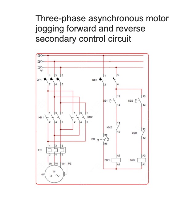
Three-phase asynchronous motor jogging forward and reverse secondary control circuit
Three-phase asynchronous motor jogging forward and reverse secondary control circuitPhysical wiring diagramCircuit diagramWorking Principle:After closing the circuit breaker QF to connect the power supply, when the SB1 start button is pressed, the current passes through the normally closed point of KM2 to supply power to the KM1 coil, causing the main contact of KM1 to close and the motor to run forward. Once the SB1 button is released, the motor stops immediately.During the forward rotation of
Master Electrician
07/03/2024
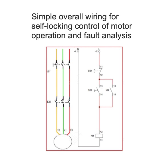
Simple overall wiring for self-locking control of motor operation and fault analysis
Simple overall wiring for self-locking control of motor operation and fault analysisPhysical wiring diagramCircuit diagramWorking Principle and Fault Analysis:1. Close QF1 and QF2 to conduct the power supply. Press the jog button SB2. The AC contactor KM coil gets electricity. The main contact closes and the auxiliary contact closes to conduct the power supply. The KM self-locking three-phase asynchronous motor starts to run.2. Release the SB1 button. The AC contactor coil loses electricity. The
Master Electrician
07/03/2024
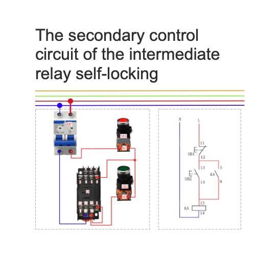
The secondary control circuit of the intermediate relay self-locking
The secondary control circuit of the intermediate relay self-locking1、Physical wiring diagram&Circuit diagram2、Operation principle Close QF to connect the power supply. Press the start button SB2, the coil of the intermediate relay gets electricity. The normally open contact 9-5 is closed to conduct the power supply. The intermediate relay is self-locked and the load starts to operate. Press the stop button SB1, the coil of the intermediate relay loses electricity. The normally open contact
Master Electrician
07/03/2024
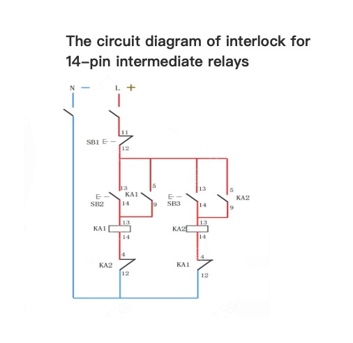
Physical diagram of interlock of 14-pin intermediate relay
Physical diagram of interlock of 14-pin intermediate relayThe circuit diagram of interlock for 14-pin intermediate relays
Master Electrician
07/02/2024
1
2
···
14
15
16
17
18
19
20
21
Source professional electrical partners, experts, and explore smart grid & energy solutions.
Inquiry
Send Now
Download
Experts Electrical is dedicated to serving the personnel in the global power industry.
Join Experts Electrical, not only can you discover power equipment and power knowledge, but also canhnd like - minded friends!