Three-phase asynchronous motor jogging forward and reverse secondary control circuit

Master Electrician
07/03/2024

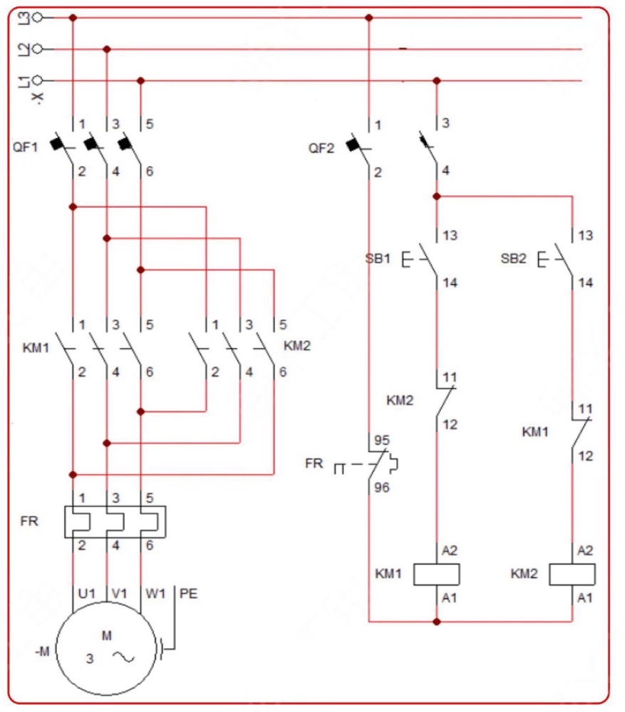
Three-phase asynchronous motor jogging forward and reverse secondary control circuit  

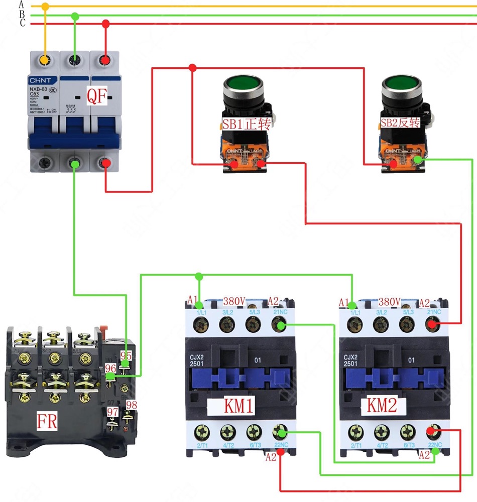
Physical wiring diagram
1719975906520.jpg

Circuit diagram

1719975985446.jpg


Working Principle:

After closing the circuit breaker QF to connect the power supply, when the SB1 start button is pressed, the current passes through the normally closed point of KM2 to supply power to the KM1 coil, causing the main contact of KM1 to close and the motor to run forward. Once the SB1 button is released, the motor stops immediately.

During the forward rotation of the motor, if the SB2 reverse start button is pressed, KM2 will not be energized. This is because the normally closed point of KM1 is connected in series in the control circuit of KM2, so the KM2 reverse contactor cannot be started when the motor is rotating forward. Only by first releasing the SB1 stop button to stop the forward KM1 AC contactor from being energized, and then pressing SB2, can KM2 work and the motor thus rotates in reverse.

Similarly, when the motor is reversing, if the SB1 forward start button is pressed, KM1 will not be energized. This is because the normally closed point of KM2 is connected in series in the control circuit of KM1, so the KM1 forward contactor cannot be started when the motor is reversing. 


Master Electrician

We aim to gather electrical knowledge and share it with others.
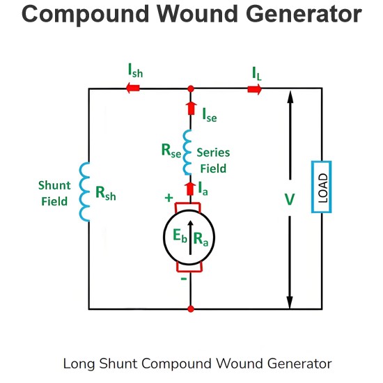
Compound Wound Generator
Compound Wound Generator FundamentalsA compound wound generator features two field windings per pole: one series-connected with few turns of thick wire, and the other shunt-connected with many turns of fine wire parallel to the armature windings.In essence, a compound generator integrates both shunt and series field windings. It is classified as:Cumulative compounded: Series winding flux reinforces shunt winding flux.Differentially compounded: Series winding flux opposes shunt winding flux.Two c
Edwiin
05/27/2025
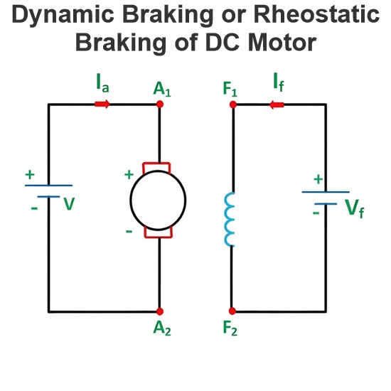
Dynamic Braking or Rheostatic Braking of DC Motor
Dynamic Braking Principles in DC MotorsIn dynamic braking, a braking resistor Rbis connected across the armature immediately after disconnecting the DC motor from the supply. The motor then functions as a generator, producing braking torque.Dynamic Braking ConfigurationsTwo connection methods enable braking operation:Separately Excited/Shunt Motor as a Separately Excited Generator:Flux is maintained constant for consistent braking performance.Self-Excited Shunt Generator:Field winding is connect
Edwiin
05/27/2025
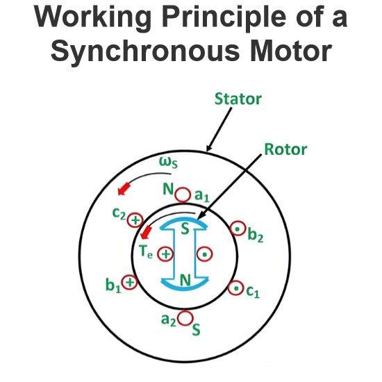
Working Principle of a Synchronous Motor
Structure and Excitation of Synchronous MotorsThe synchronous motor consists of two primary components: the stator (stationary part) and the rotor (rotating part). The stator is energized by a three-phase AC supply, while the rotor is excited by a DC supply.Excitation Principle:Excitation refers to the process of inducing magnetic fields in both the stator and rotor, transforming them into electromagnets. This magnetic coupling is essential for converting electrical energy into mechanical rotati
Edwiin
05/26/2025
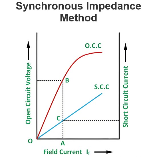
Synchronous Impedance Method
The Synchronous Impedance Method, also known as the EMF Method, replaces the impact of armature reaction with an equivalent imaginary reactance. To calculate voltage regulation using this method, the following data are required: armature resistance per phase, the Open-Circuit Characteristic (OCC) curve depicting the relationship between open-circuit voltage and field current, and the Short-Circuit Characteristic (SCC) curve showing the relationship between short-circuit current and field current
Edwiin
05/26/2025
Inquiry
Download
Experts Electrical is dedicated to serving the personnel in the global power industry.
Join Experts Electrical, not only can you discover power equipment and power knowledge, but also canhnd like - minded friends!