The secondary control circuit of the intermediate relay self-locking
The secondary control circuit of the intermediate relay self-locking
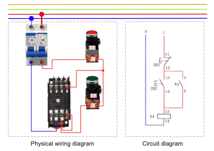
1、Physical wiring diagram&Circuit diagram
2、Operation principle
Close QF to connect the power supply. Press the start button SB2, the coil of the intermediate relay gets electricity. The normally open contact 9-5 is closed to conduct the power supply. The intermediate relay is self-locked and the load starts to operate.
Press the stop button SB1, the coil of the intermediate relay loses electricity. The normally open contact 9-5 is disconnected from the power supply and the load stops operating.
3、Note
The functions of the intermediate relay
1. The contacts of the intermediate relay have a certain load-carrying capacity. When the load capacity is small, it can be used instead of a small contactor, such as the control of electric rolling shutters and some small household appliances. The advantage is that it can not only achieve the purpose of control, but also save space and make the control part of the electrical appliance more exquisite.
2. Increase the number of contacts
This is a common usage of the intermediate relay. For example, in the circuit control system, when the contact of one contactor needs to control multiple contactors or other components, an intermediate relay is added to the line.
3. Increase the contact capacity
We know that although the contact capacity of the intermediate relay is not large, it also has a certain load-carrying capacity, and the current required for its drive is very small. Therefore, the intermediate relay can be used to expand the contact capacity. For example, the output of the induction switch and the transistor cannot be directly used to control the electrical components with a large load. Instead, the intermediate relay is used in the control circuit to control other loads through the intermediate relay to achieve the goal of expanding the control capacity.
We aim to gather electrical knowledge and share it with others.
