• 550kV HV SF6 Circuit Breaker
550kV HV SF6 Circuit Breaker
discuss personally
Model
LW55B-550/4000-63
Basic info
Brand Wone
Model NO. 550kV SF6 Circuit Breaker
Rated voltage 550kV
Rated normal current 6300A
Series LW55B
Product Detail

Description:

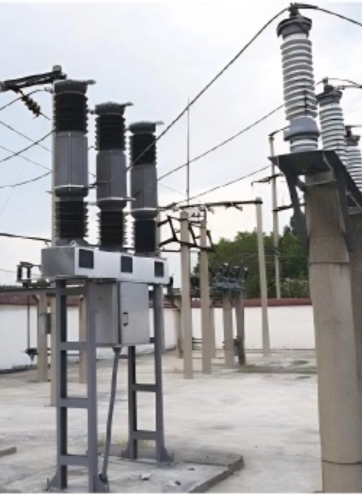
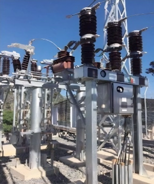
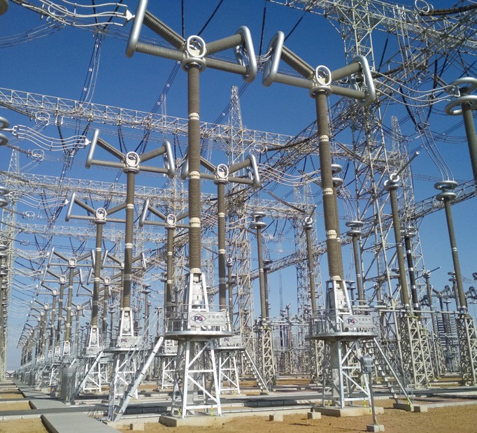
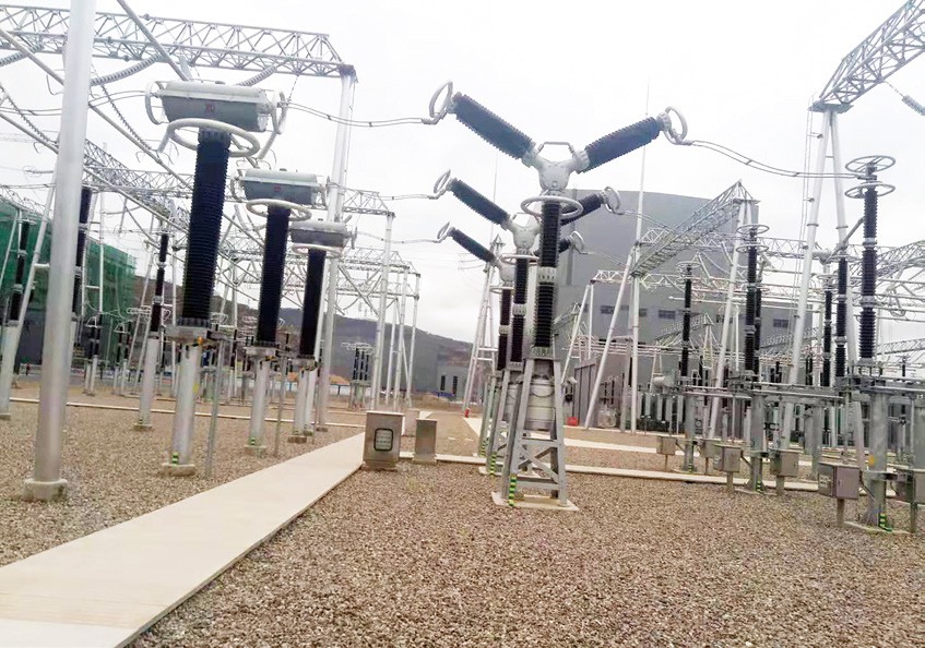
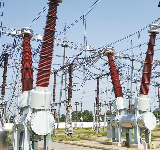
LW55B-550/Y4000-50 tank type SF6 circuit breaker is the 3-phase AC transmission equipment.Used in the power system of 550KV, can be realized the controlling, measurement and protection. It is composed of circuit breaker, current transformer and bushings for the wire’s incoming and outgoing. Circuit breaker is a single fracture design, equipped with the first domestic integrated block, high-power hydraulic operating mechanism, all of the hydraulic pipes built-in, no leakage.

This is a product based on new technology research and development, and its performance is at the leading level in the world.


Main Features:


  • Circuit breaker arcing chamber is a single fracture design, simple and reasonable structure, high technical content.

  • Strong breaking capacity, long contact electrical life(rated short circuit breaking up to 20 times), long service period.

  • As for the rectifier circuit breaker, except for the bushing unit is packaged independently, arcing unit, hydraulic operating mechanism, current transformer and other components are packaged as a whole unit, without on-site docking and adjustment, easy installation.

  • Circuit breaker unit is installed on site without opening the chamber, which can be filled the SF6 gas directly, to avoid the intrusion of dust and foreign bodies

  • There are almost no external pipe for this new type of hydraulic operating mechanism, the possibility of oil leakage is reduced.

  • When operating the oil pressure, hydraulic operating mechanism is controlled by the pressure switch automatically, can be maintained constantly the rated oil pressure without being affected by ambient temperature, at the same time, the relief valve in the mechanism can be exempted from the risk of overpressure.

  • After the loss of pressure, hydraulic operating mechanism has the function of not slowing points when the pressure is reconstructed.

  • The closing resistance of the product can be installed or removed according to the user’s requirements.

Technical Parameters:

1720766371937.png

What are the requirements for monitoring the gas decomposition products of the SF6 tank circuit breaker?


During the normal operation and interruption processes of a circuit breaker, SF₆ gas can decompose, producing various decomposition products such as SF₄, S₂F₂, SOF₂, HF, and SO₂. These decomposition products are often corrosive, toxic, or irritating, and therefore require monitoring.If the concentration of these decomposition products exceeds certain limits, it may indicate abnormal discharges or other faults within the arc quenching chamber. Timely maintenance and handling are necessary to prevent further damage to the equipment and to safeguard personnel health.


Know your supplier
Wone
Main Categories
High voltage/Low voltage/Wire cable/Instrument meters/New energy/Tester/Production equipment/Generator/Electrical fittings/Integrated Electrical Equipment
Business Type
Design/Manufacture/Sales
Highest Annual Export (USD)
$50,000,000
Professional Experience
1 years
Workplace
65666m²m²
占位
占位
Related Products
Related Knowledges
The design of the three-purpose grounding transformer
Underground Power Cable Transmission LinesDirect - buried power cable lines have large ground - distributed capacitance, causing high single - phase - to - ground short - circuit capacitive current. For 10 kV lines, if this current exceeds 10 A, arcs hardly self - extinguish, risking arc overvoltage and endangering line equipment. Arc extinction is thus necessary. With a Dyn - connected main transformer, an arc - suppression coil on the secondary neutral point suffices. For Yd - connected ones,
Dyson
06/12/2025
Failure Analysis and Design Optimization of Conventional Grounding Transformers
I. Core Cause of Damage: Electrodynamic Impact (Complying with GB/T 1094.5 / IEC 60076-5)The direct cause of high-voltage winding end collapse is the instantaneous electrodynamic impact induced by short-circuit current. When a single-phase grounding fault occurs in the system (such as lightning overvoltage, insulation breakdown, etc.), the grounding transformer, as the fault current path, withstands high-amplitude and steep-rise-rate short-circuit currents. According to Ampère's force law
Felix Spark
06/12/2025
Analysis of Grounding Transformer Operational Behavior Under System Single-Phase-to-Ground Fault Conditions
1 Theoretical AnalysisIn distribution networks, grounding transformers serve two key roles: powering low - voltage loads and connecting arc - suppression coils at neutrals for grounding protection. Grounding faults, the most common distribution network fault, heavily impact transformers’ operating characteristics, causing sharp changes in electromagnetic parameters and status.To study transformers’ dynamic behaviors under single - phase grounding faults, build this model: Assume a tr
Felix Spark
06/12/2025
Design Calculations for Neutral Grounding Schemes and Grounding Transformer Sizing in Utility-Scale Solar PV Plants
1 Classification of Neutral Grounding Methods for Solar Photovoltaic Power StationsInfluenced by differences in voltage levels and grid structures across regions, the neutral grounding methods of power systems are mainly categorized into non-effective grounding and effective grounding. Non-effective grounding includes neutral grounding via arc suppression coils and neutral ungrounded systems, while effective grounding comprises neutral solid grounding and neutral grounding via resistors. The sel
Dyson
06/12/2025
Zero-Sequence Impedance Characterization of Dry-Type Grounding Transformer with ZN Connection
In a neutral-insulated three-phase power system, an earthing transformer provides an artificial neutral point, which can be solidly earthed or earthed via reactors/arc suppression coils. The ZNyn11 connection is typical, where zero-sequence magnetomotive forces in the inner/outer half-windings of the same core column cancel out, balancing fault currents in series windings and minimizing zero-sequence leakage flux/impedance.Zero-sequence impedance is critical: it determines fault current magnitud
Dyson
06/12/2025
Case Analysis on Maloperation of Grounding Transformer Overcurrent Protection Relay
The neutral grounding mode refers to the connection between the power system neutral point and ground. In China's 35 kV and below systems, common methods include ungrounded neutral, arc-suppression coil grounding, and small-resistance grounding. The ungrounded mode is widely used as it allows short-term operation during single-phase grounding faults, while small-resistance grounding has become mainstream for its fast fault removal and overvoltage limitation. Many substations install grounding tr
Felix Spark
06/12/2025
×
Inquiry
Download
Experts Electrical is dedicated to serving the personnel in the global power industry.
Join Experts Electrical, not only can you discover power equipment and power knowledge, but also canhnd like - minded friends!
商品视频播放