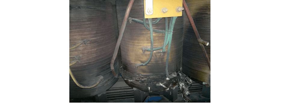
Failure Analysis and Design Optimization of Conventional Grounding Transformers

Felix Spark
06/12/2025

I. Core Cause of Damage: Electrodynamic Impact (Complying with GB/T 1094.5 / IEC 60076-5)
The direct cause of high-voltage winding end collapse is the instantaneous electrodynamic impact induced by short-circuit current. When a single-phase grounding fault occurs in the system (such as lightning overvoltage, insulation breakdown, etc.), the grounding transformer, as the fault current path, withstands high-amplitude and steep-rise-rate short-circuit currents. According to Ampère's force law, winding conductors are subjected to radial (inward compression) and axial (tensile/compressive) electrodynamic forces in a strong magnetic field. If the electrodynamic force exceeds the mechanical strength limit of the winding structure (conductors, spacers, press plates, binding systems), it will cause irreversible deformation, displacement, or distortion of the windings, eventually manifesting as winding end collapse—a typical failure mode of transformer-type equipment under short-circuit faults.
II. Associated Fault Triggers: Resonant Overvoltage and Energization with Residual Faults (Complying with Overvoltage Protection Standards such as DL/T 620 / IEC 60099)
  • System Resonant Overvoltage (Ferroresonance / Linear Resonance)
    Improper matching of system parameters (line capacitance, PT inductance, arc suppression coil inductance, etc.) can trigger ferroresonance or linear resonance, generating persistent overvoltage. This overvoltage repeatedly acts on insulation weak points (aged insulators, arresters, bushings, etc.), leading to intermittent arc grounding or repeated breakdowns, causing the grounding transformer to withstand high-frequency impact currents. This not only directly produces electrodynamic impacts but also accelerates the thermal and electrical aging of winding insulation (inter-turn, inter-layer, and main insulation), significantly reducing its dielectric strength and mechanical strength, making it more prone to collapse under subsequent impacts or normal operation.
  • Energization with Persistent Faults after Lightning Strike
    After a lightning strike causes a permanent grounding fault in the line, if the fault point is not isolated (e.g., the circuit breaker does not trip or fault indication is unclear), maintenance personnel mistakenly restore power (energization with faults), forcing the grounding transformer to continuously pass power-frequency fault current (far exceeding the design limit). Sustained overcurrent triggers the I²Rt Joule heating effect, causing the winding temperature to rise sharply beyond the insulation tolerance limit (e.g., 105°C for Class A), rapidly leading to thermal aging, carbonization, and loss of insulation performance, eventually resulting in winding short-circuit and burnout (thermal collapse). This condition causes devastating damage to the equipment.

III. Optimization Scheme: Enhancing Equipment Tolerance and Perfecting Protection Strategies (Integrating Equipment Selection, Relay Protection, and Condition Monitoring Standards)

  • Improving Equipment Body Short-Circuit Resistance (Complying with GB/T 1094.5 / IEC 60076-5)
    • Selection Requirements: Prioritize high short-circuit resistance models verified by strict short-circuit withstand tests (e.g., IEC 60076-5) for subsequent purchases, focusing on winding structure design (reinforced press plates, axial clamping systems, radial support structures, transposition conductor processes), material strength, and manufacturing processes.
    • Optional Series Current-Limiting Reactor: Install a current-limiting reactor in the neutral circuit of the grounding transformer to effectively suppress the amplitude and rise rate of fault currents, reducing electrodynamic impacts on windings. The impact on the system grounding mode and relay protection must be verified simultaneously.
  • Optimizing Relay Protection Configuration and Setting (Complying with Relay Protection Standards DL/T 584 / DL/T 559)
    • Optimization of Grounding Transformer Body Protection Settings:
      • Setting Principle: The overcurrent protection settings (zero-sequence overcurrent, inverse-time overcurrent) of the grounding transformer must be strictly lower than the equipment's thermal and dynamic stability limits (calculated per GB/T 1094.5).
      • Gradation Coordination: The protection time delay of the grounding transformer (e.g., 100A/10s) must reliably coordinate with the upstream line protection (outgoing circuit breaker). Ensure that the line protection (zero-sequence Stage I: 0.2s, Stage II: 0.7s) can quickly clear grounding faults on the line, preventing the grounding transformer from enduring unnecessary stress. The grounding transformer protection, as a close backup, should have an operation time delay greater than the longest time delay of the line protection (including the gradation Δt).
  • Strengthening Fault Fast-Clearing Capability (Complying with DL/T 584 / DL/T 559)
    • Directional Zero-Sequence Protection Configuration: Deploy and reliably activate directional zero-sequence current protection (Stage I/II) in line protection. The direction element accurately distinguishes between faulted and non-faulted lines, ensuring that the faulted line circuit breaker trips reliably within ≤0.2s during single-phase grounding faults, completely isolating the fault source—this is the core protection measure to prevent grounding transformer damage.
  • Deploying Intelligent On-Line Monitoring and Early Warning Systems (Complying with Condition Monitoring Standard DL/T 1709.1)
    • Real-Time Winding Hot Spot Temperature Monitoring: Install optical fiber or platinum resistance temperature sensors at key positions of the high-voltage winding ends to achieve real-time monitoring with ±1~2℃ accuracy. Set multi-level alarms (warning/alert) and tripping thresholds (calculated based on insulation class thermal models), automatically triggering protection actions when limits are exceeded to prevent thermal collapse.
    • Neutral Point Electrical Parameter Monitoring and Asymmetry Alarm: Continuously monitor neutral point current and system displacement voltage (zero-sequence voltage), and configure asymmetry over-limit alarm functions. When persistent/frequent abnormal neutral point electrical parameters are detected (indicating intermittent grounding, resonance, or insulation degradation), issue immediate warnings for early fault intervention.

Optimization Conclusions and Implementation Recommendations

  • Conclusion Summary
    • The direct cause of the accident is that the electrodynamic force generated by the single-phase grounding fault current exceeds the mechanical strength limit of the windings.
    • Deep-level triggers include: ① Intermittent impacts caused by system resonant overvoltage accelerating insulation aging; ② Thermal collapse due to energization with permanent faults after lightning strikes.
    • Systematic optimization should focus on three aspects:
      • Equipment Strengthening: Select high short-circuit resistance equipment or install current-limiting reactors to enhance electrodynamic tolerance.
      • Protection Coordination: Precisely set protection values (≤equipment tolerance limits) and ensure gradation coordination with directional zero-sequence protection (Stage I ≤0.2s).
      • Condition Early Warning: Deploy high-precision temperature monitoring (±1~2℃) and neutral point electrical parameter alarm systems for early fault protection.
  • Implementation Recommendations
    • Immediate implementation of protection setting adjustments, directional protection activation, and monitoring system installation.
    • Plan equipment body upgrades in conjunction with service life cycles and technical transformation schedules.
    • Incorporate this scheme into operation regulations and anti-accident measures, strictly prohibiting energization with grounding faults, and thoroughly investigating fault points before restoring power after lightning strikes.
Felix Spark

Hey there! I'm an electrical engineer specializing in Failure and Maintenance. I've dedicated my career to ensuring the seamless operation of electrical systems. I excel at diagnosing complex electrical failures, from malfunctioning industrial motors to glitchy power distribution networks. Using state - of - the - art diagnostic tools and my in - depth knowledge, I pinpoint issues quickly. On this platform, I'm eager to share my insights, exchange ideas, and collaborate with fellow experts. Let's work together to enhance the reliability of electrical setups.

Inquiry
Download
Experts Electrical is dedicated to serving the personnel in the global power industry.
Join Experts Electrical, not only can you discover power equipment and power knowledge, but also canhnd like - minded friends!