The neutral grounding mode refers to the connection between the power system neutral point and ground. In China's 35 kV and below systems, common methods include ungrounded neutral, arc-suppression coil grounding, and small-resistance grounding. The ungrounded mode is widely used as it allows short-term operation during single-phase grounding faults, while small-resistance grounding has become mainstream for its fast fault removal and overvoltage limitation. Many substations install grounding transformers to retrofit neutral grounding, but changed fault characteristics affect relay protection, risking maloperation or refusal.
This paper introduces grounding transformer principles and characteristics, expounds current protection configuration/setting in small-resistance systems, analyzes maloperation causes, and takes a single-phase grounding case to dissect protection actions and failure roots. It provides references for fault handling/prevention, deepens maintenance staff understanding, enhances troubleshooting efficiency, and eliminates potential hazards.
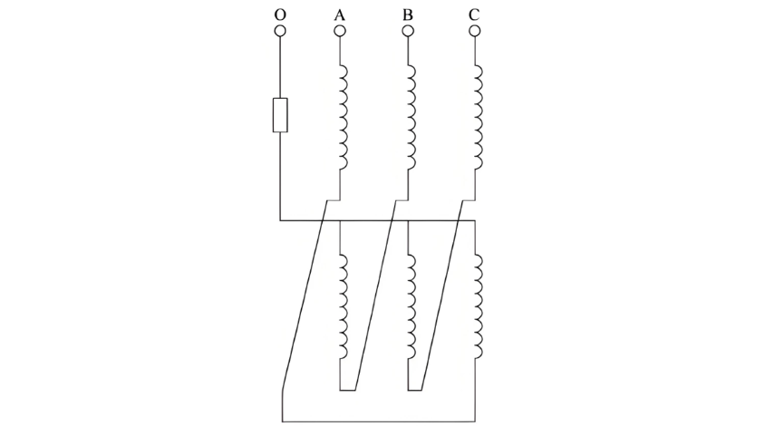
Working Principle of the Earthing Transformer
During the transformation of a substation with a delta - connected, neutral - ungrounded system to a small - resistance grounding system, in order to introduce a neutral point, the most common practice is to add an earthing transformer at the busbar. Currently, a Z - type earthing transformer is generally selected to introduce the grounding point . Next, the working principle of the Z - type earthing transformer will be analyzed.
The Z - type earthing transformer is structurally similar to an ordinary power transformer. However, the winding on each phase core is divided into two parts with equal turns, upper and lower, which are connected in a zig - zag shape. Its wiring method is shown in Figure 1.
When a ground short - circuit occurs, zero - sequence current flows in via the neutral point. The Z - type earthing transformer’s zig - zag connection makes upper and lower winding zero - sequence currents oppose each other, canceling magnetic fluxes and minimizing zero - sequence impedance to avoid excessive arc - grounding overvoltage. For positive/negative - sequence currents, its conventional transformer - like electromagnetic properties create high impedance, restricting their flow.
Under normal operation, the earthing transformer runs near no - load (no secondary load). During a ground fault, positive, negative, and zero - sequence fault currents pass through it. Owing to “high positive/negative - sequence, low zero - sequence impedance”, the protection device mainly measures the grid’s zero - sequence current.
2 Configuration and Analysis of Current Protection for Earthing Transformers
Earthing transformer current protection typically uses phase - to - phase and zero - sequence current protection. Here’s the breakdown:
2.1 Setting of Phase - to - Phase Current Protection
2.1.1 Setting Principles
This protection includes instantaneous trip and over - current protection:
- Instantaneous Trip: Coordinate with the power supply transformer’s backup over - current protection on the same side. Ensure sensitivity during two - phase short - circuits (minimum operation mode) and avoid inrush currents (7–10× earthing transformer rated current) and low - voltage side fault currents.
- Over - Current Protection: Set to avoid the earthing transformer’s rated current and maximum fault phase current during external single - phase grounding, ensuring reliability.
- Operation Logic: Instantaneous trip acts immediately (no delay); over - current protection (backup for phase - to - phase shorts) has a short delay and lower settings for leveled coordination.
2.1.2 Tripping Modes
Based on the earthing transformer’s connection to the power supply transformer:
- Connected to the low - voltage bus: Instantaneous trip/over - current protection trips the same - side circuit breaker to isolate faults quickly.
- Connected to the low - voltage lead: Protection trips all - side circuit breakers to cut the fault path and prevent escalation.
2.2 Setting of Zero - Sequence Current Protection for Earthing Transformers
2.2.1 Setting Principles
- The current setting value shall ensure sufficient sensitivity when a single - phase - to - ground fault occurs.
- Cooperate with the setting value of the long - delay protection for the full - line sensitivity of the lower - level zero - sequence current protection.
- For the first time limit of zero - sequence current, consideration shall be given to avoiding the successive occurrence of single - phase - to - ground faults on two lines.
- The operating time shall be longer than the maximum operating time of the Section Ⅱ of zero - sequence current of each connected component of the bus.
Since the zero - sequence current protection of the earthing transformer does not serve as the main protection, there are three time limits, which are shown as follows:
In the formula: t01, t02, t03 are the 1st, 2nd, and 3rd time limits of the zero - sequence current protection of the earthing transformer respectively; t0I' is the time setting value of Section I of the zero - sequence current of the outgoing line; t0II' is the longest time setting value of Section II of the zero - sequence current protection of all equipment on the busbar except the earthing transformer; Δt is set as 0.2 - 0.5 s.
2.2.2 Tripping Modes
-
When the earthing transformer is connected to the corresponding busbar of the substation, the zero - sequence current protection operates: the 1st time limit trips the bus tie circuit breaker or section circuit breaker and blocks the automatic standby power supply input device (referred to as "automatic standby input" for short); the 2nd time limit trips the circuit breakers on the same side of the earthing transformer and the power supply transformer.
-
When the earthing transformer is connected to the corresponding lead of the power supply transformer, the zero - sequence current protection operates: the 1st time limit trips the bus tie circuit breaker or section circuit breaker and blocks the automatic standby input; the 2nd time limit trips the circuit breaker on the same side of the power supply transformer; the 3rd time limit trips the circuit breakers on all sides of the power supply transformer .
2.3 Analysis of Current Protection Operation for Earthing Transformers
Analysis of the earthing transformer protection configuration shows significant differences in tripping modes between phase - to - phase and zero - sequence current protections: zero - sequence protection blocks auto - standby input during operation, while phase - to - phase protection does not.
If the zero - sequence current measured by the protection device reaches the operation value and a ground fault occurs (with the earthing transformer as the only zero - sequence current path in a small - resistance grounding system), the device detects the fault but cannot locate it. If the fault is on the outgoing line, after the protection trips the earthing transformer, the auto - standby input switches to the standby busbar. If the standby busbar recloses onto the faulty line, the earthing transformer on it still detects zero - sequence current, triggering another trip. Since the auto - standby input hasn’t finished charging, the outage range may expand. Thus, zero - sequence protection must block auto - standby input.
When phase - to - phase protection acts (but zero - sequence protection doesn’t), the device judges a phase - to - phase short - circuit in the earthing transformer itself. It trips the earthing transformer, parallel - trips the power supply transformer’s same - side circuit breaker, and the auto - standby input switches to the standby busbar. As the fault is on the tripped earthing transformer, the standby busbar reconnects to the normal line, restoring power.
In summary, phase - to - phase and zero - sequence current protections of earthing transformers differ greatly in fault cause and location judgment, requiring distinct settings and configurations. However, during a ground short - circuit, phase - to - phase protection may misoperate due to measured zero - sequence components. Given their different auto - standby input logics, misoperation may expand the fault range or even cause a full - substation blackout.
3 Case Analysis
3.1 Fault Process
The primary wiring diagram of a 110 kV substation is shown in Figure 2. Before the fault, the low-voltage side 018 circuit breaker of Transformer 1 was closed, the low-voltage side 032 circuit breaker of Transformer 2 was closed, and the 034 circuit breaker was in the test position.
At 06:14 on July 30, 2023, the over-current I section protection of the No. 2 earthing transformer activated, tripping the No. 2 earthing transformer 022 circuit breaker. Meanwhile, it interlocked to cut off the low-voltage side 032 circuit breaker of Transformer 2, causing the 10 kV Section II and III busbars to lose power. The automatic standby power supply (auto-standby) device operated to close the 10 kV Section I/II bus tie 020 circuit breaker.
At 06:36, the over-current I section protection of the No. 1 earthing transformer activated, tripping the No. 1 earthing transformer 015 circuit breaker and interlocking to cut off the low-voltage side 018 circuit breaker of Transformer 1, leading to power loss in all 10 kV Section I, II, and III busbars. The auto-standby device then closed the low-voltage side 032 circuit breaker of Transformer 2 and the No. 2 earthing transformer 022 circuit breaker. However, the fault persisted, triggering the over-current I section protection of the No. 2 earthing transformer again. The 022 circuit breaker tripped and interlocked to cut off the 032 circuit breaker, eventually causing a complete power outage in the substation's 10 kV system.
3.2 On-site Equipment Inspection Results
Primary equipment inspection findings:
-
Earthing transformer body: No abnormalities were found in No.1 and No.2 earthing transformers, with no obvious fault traces in windings or cores.
-
10 kV Section III bus PT interval (040 switchgear):
- Obvious water stains on the top cover of the switchgear cabinet, indicating rainwater infiltration.
- Severe ablation at the C-phase position of the handcart chamber shutter baffle, with two through-holes on the upper shutter.
- The C-phase upper contact box and static contact were charred and damaged, with liquid water accumulated inside the box.
- Arc burn marks on the C-phase upper/lower moving contacts of the arrester handcart, annealed springs, and damaged contact arm insulating cylinders.
- The outer insulating sleeve of the C-phase busbar in the bus chamber was burned and cracked. Water stain penetration was observed in the C-phase area of the bus chamber backplate, and water droplets were condensed on the live display sensor.
- A small amount of water accumulated at the bottom of the voltage transformer chamber, while the three-phase PTs showed no obvious external abnormalities.
Rainwater leakage from the steel support above the 10 kV Section III bus PT chamber infiltrated the switchgear, degrading insulation and causing a C-phase discharge that evolved into a metallic ground fault. In the low-resistance grounding system, the No. 2 earthing transformer detected zero-sequence currents of ~4.3 A/phase (exceeding the 2.5 A overcurrent I-section setting), triggering tripping. The overcurrent protection does not block the 10 kV auto-standby, leading to repeated operations. The final trip left the auto-standby uncharged, causing a complete 10 kV outage.
Key contributing factor: The "phase current zero-sequence cancellation" control word was disabled (set to "0"), preventing software filtering of zero-sequence components in phase currents. With a 13 A zero-sequence current, the overcurrent protection misoperated. Properly enabled, this control would have prevented the fault. Instead, the zero-sequence overcurrent protection I-section (set at 1.4 A) operated: 1st time-limit tripped the bus tie and blocked auto-standby; 2nd time-limit tripped the earthing and main transformer breakers, isolating Sections II/III while Section I remained powered.
Root cause: Disabled zero-sequence cancellation control word allowed phase current misinterpretation.
4 Conclusion
This paper outlines earthing transformer protection settings, analyzes misoperation risks under high zero-sequence currents, and presents a case study. To prevent recurrence:
- Enable software-based zero-sequence cancellation features (e.g., "phase current zero-sequence cancellation" control word) in low-resistance grounding systems.
- If such features are unavailable, optimize coordination between overcurrent and zero-sequence protection settings.
Key takeaway: Proactive configuration of protection software is critical for preventing misoperations during ground faults.