Definition and Principle of Impedance Relay (Distance Relay)
An impedance relay, also known as a distance relay, is a voltage-controlled protective device whose operation depends on the electrical distance (impedance) between the fault point and the relay’s installation position. It functions by measuring the impedance of the faulty section and comparing it with a pre-set threshold.
Working Mechanism
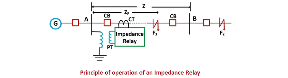
- Measurement and Comparison: The relay continuously monitors line voltage (via potential transformers, PTs) and current (via current transformers, CTs) to calculate the impedance (Z = V/I).
- Fault Response: If the measured impedance is lower than the relay’s setting (indicating a fault within the protected zone), it triggers a tripping command to the circuit breaker. Under normal conditions, the line impedance is high (voltage >> current), keeping the relay inactive. When a fault occurs, current surges and voltage drops, reducing the impedance and activating the relay.
Operational Principle
In normal operation, the voltage-to-current ratio (impedance) remains above the relay’s threshold. During a fault (e.g., F1 on line AB), the impedance drops below the setting. For example, if the relay is installed to protect line AB with a normal impedance Z, a fault reduces the impedance, prompting the relay to trip the breaker. If the fault lies outside the protected zone (e.g., beyond AB), the impedance remains high, and the relay stays unactivated.
Operating Characteristics
The relay comprises two key components:
- Current Operating Element: Generates a deflecting torque proportional to the current.
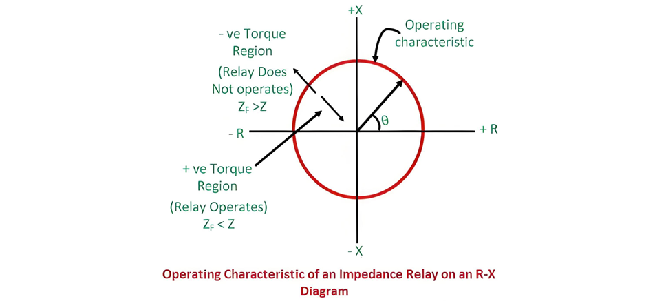
- Voltage Restraining Element: Produces a restoring torque based on the voltage. The torque balance equation is:k1I2 −k2VIcos(θ−ϕ)=0 is the phase angle between voltage and current, and θ is the relay’s maximum torque angle. On an impedance diagram, the relay’s operating characteristic appears as a circle centered at the origin, with a radius equal to the setting impedance. This circular characteristic ensures sensitivity to both impedance magnitude and phase, enabling reliable discrimination between in-zone and out-of-zone faults.

-K3 represents the relay's spring effect. At normal operation, net torque = 0 with V and I values.

If the spring control effect becomes neglected, the equation becomes

The figure shows operating characteristics with voltage and current; dashed line denotes constant line impedance.
The figure below depicts the impedance relay's operating characteristic. The region above the characteristic line represents positive torque, where the line impedance exceeds that of the faulty section, triggering relay operation. Conversely, the negative torque region (below the line) indicates the fault impedance surpasses the line impedance, keeping the relay inactive. This distinction enables precise fault detection by comparing measured impedance against the pre-set threshold, ensuring reliable protection in power systems.
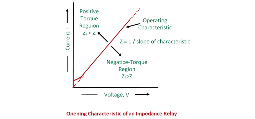
The circle's radius represents line impedance; the X-R phase angle indicates vector position. Impedance < radius = positive torque (relay operates); impedance > radius = negative torque (relay inactive). This visual distinction ensures rapid fault detection in power systems.
This relay is categorized as a high-speed relay.
Electromagnetic Induction Relay
Torque in this relay arises from electromagnetic interactions between voltage and current, which are compared for operation. In its circuit, Solenoid B—powered by a potential transformer (PT)—generates clockwise torque, pulling plunger P2 downward. A spring on P2 applies restraining force, creating clockwise mechanical torque.
Solenoid A, excited by a current transformer (CT), produces clockwise deflecting (pick-up) torque that moves plunger P1 downward. Under normal conditions, relay contacts stay open. During a protective zone fault, surging system current increases Solenoid A’s torque while reducing Solenoid B’s restoring torque. This imbalance rotates the relay’s balance arms, closing contacts to initiate protection. The design ensures rapid response to faults via torque comparison between electromagnetic and mechanical forces.
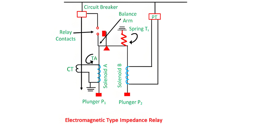
The force exerted by solenoid A (the current element) is proportional to I2, while that from solenoid B (the voltage element) is proportional to V2. As a result, the relay will activate when the current-derived force exceeds the voltage-derived force.

The constants k1 and k2 depend on the ampere-turns of the two solenoids and the ratios of the instrument transformers. Relay settings can be adjusted via tappings on the coils.
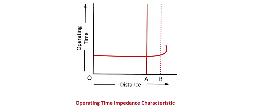
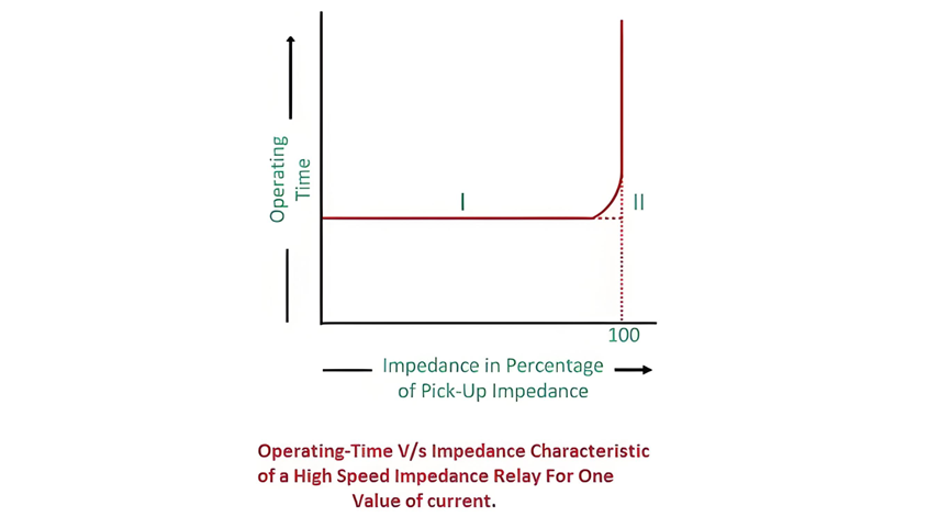
On the characteristic curve, the y-axis denotes the relay’s operating time, while the x-axis represents impedance. Notably, the relay’s operating time remains constant (indicating instantaneous action) for impedances within the preset protection zone. At the predetermined distance (corresponding to the set impedance), voltage and current values stabilize; beyond this point, the measured impedance theoretically becomes infinite, meaning the relay remains inactive for faults outside its protective scope. This linear relationship between impedance and operating time ensures reliable, rapid fault detection within the defined zone.
Induction Type Impedance Relay
The circuit diagram of an induction-type impedance relay is illustrated below. This relay incorporates both current and voltage elements, featuring an aluminium disc that rotates between electromagnets.
The upper electromagnet contains two distinct windings: the primary winding is connected to the secondary coil of a current transformer (CT), while the secondary winding is linked to a potential transformer (PT). The current setting of the primary winding can be adjusted via a plug bridge positioned beneath the relay, allowing for precise calibration of the relay’s sensitivity. The voltage element, energized by the PT, generates a magnetic field that interacts with the current-derived field from the CT.
This interaction induces eddy currents in the aluminium disc, producing a torque that drives its rotation. Under normal operating conditions, the disc remains stationary due to balanced torques; during a fault, the current surge unbalances the torques, causing the disc to rotate and trigger the relay contacts. This design ensures reliable impedance-based fault detection in power systems.
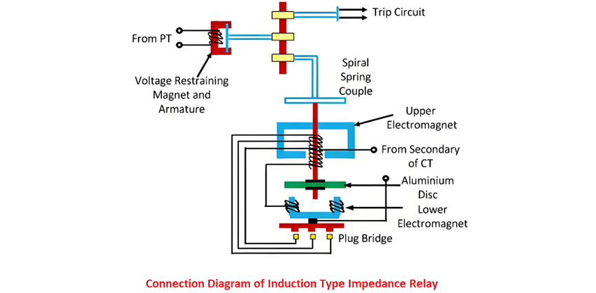
The electromagnets in the relay are connected in series, with their induced fluxes generating rotational torque that drives the aluminium disc. A permanent magnet provides both controlling and braking torque to stabilize the disc’s motion.
Under normal operation, the force on the armature exceeds the torque from the induction element, keeping the trip contacts open. When a system fault occurs, the current through the electromagnets surges, causing the aluminium disc to rotate. The disc’s rotational speed is directly proportional to the fault current, winding a spring as it turns. This rotational motion gradually overcomes the restraining torque from the permanent magnet.
Once the disc’s rotation reaches a critical threshold (corresponding to the preset impedance), the trip contacts close, initiating the protective response. This design ensures that the relay reacts swiftly to faults while maintaining stability during normal operation, with the permanent magnet providing essential control over the disc’s acceleration and braking to prevent false tripping.
The rotation angle of the relay's disc relies on the armature force, which is directly proportional to the applied voltage. Hence, voltage dictates the rotation angle.
Time-Characteristic of High-Speed Impedance Relay
The figure depicts that the relay remains inactive for values exceeding 100% of the pickup threshold. Curve 1 represents the actual operational characteristic, while Curve 2 offers a simplified model of Curve 1. This design ensures rapid response to faults within the preset range while maintaining stability under normal conditions. The relay's high-speed operation is critical for minimizing damage in power systems, with the simplified curve facilitating easier implementation and analysis in protective relay settings.
Drawbacks of Plain Impedance Relay
The following are the key disadvantages of impedance relays:
-
Lack of Directional Discrimination
The relay responds to impedance changes on both sides of the current transformer (CT) and potential transformer (PT). This makes it difficult for circuit breakers to distinguish between internal faults (within the protected zone) and external faults (outside the zone), potentially leading to unnecessary tripping or delayed isolation of faults.
-
Sensitivity to Arc Resistance
The relay’s operation is significantly influenced by arc resistance during faults. Arc resistance introduces additional impedance, which can mask the true fault impedance and cause the relay to either under-react (fail to trip for internal faults) or over-react (falsely trip for external faults).
-
Vulnerability to Power Swings
Impedance relays are highly sensitive to power swings—periodic oscillations in voltage and current caused by system disturbances (e.g., sudden load changes or generator instability). Power swings can mimic fault conditions by altering the measured impedance, leading to false tripping or delayed operation.
-
Non-Directional Operation
The relay trips whenever the measured impedance falls below the preset threshold, regardless of the fault direction. This means it cannot differentiate between forward faults (within the protected line) and backward faults (toward the power source), limiting its applicability in complex, multi-source power systems.