Vacuum Condition Measurement In Vacuum Interrupter By Mechanical Pressure Monitoring Method

Vacuum Condition Monitoring in Vacuum Interrupters
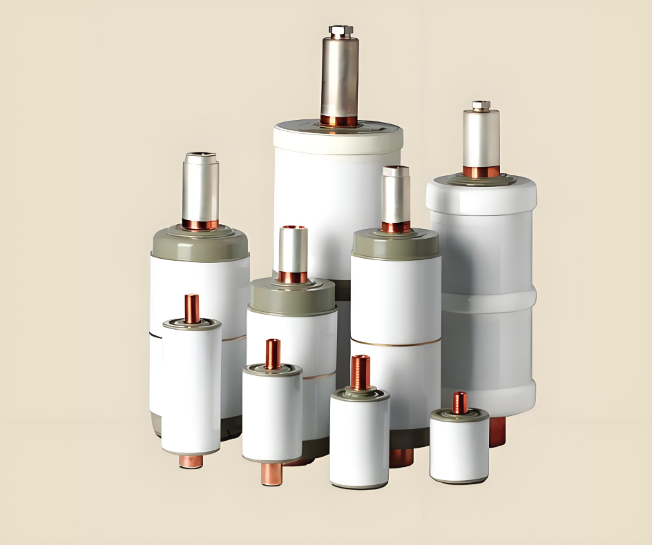
Vacuum interrupters (VIs) serve as the primary circuit interruption medium for medium voltage power systems and are increasingly utilized in low, medium, and high-voltage systems. The performance of VIs hinges on maintaining an internal pressure below 10 hPa (where 1 hPa equals 100 Pa or 0.75 torr). Prior to leaving the factory, VIs are tested to ensure their internal pressure is ≤10^-3 hPa.
The performance of a VI correlates with its vacuum level; however, it isn't simply proportional to the internal pressure. Instead, the pressure inside a VI can be categorized into three groups:
• Low Pressure: Below 10^-6 hPa
• Mid-Range Pressure: From approximately 10^-3 hPa up to the Paschen minimum pressure
• High Pressure: Generally indicative of a failure leading to exposure to air
In the low-pressure range, VIs function effectively. However, in the mid-range, both dielectric strength and interruption capabilities degrade, a degradation that continues into the "up-to-air" range. Interestingly, while dielectric performance is at its lowest in the mid-range pressures, it actually improves somewhat in the up-to-air range—though not to the level observed in the low-pressure range.
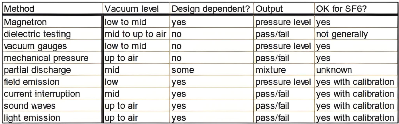
It's crucial to recognize that none of the discussed monitoring techniques cover the entire range of pressures within a VI, from low-pressure to up-to-air conditions. Each technique applies to a specific range, detailed in the text and summarized in Table 1. Additionally, the effectiveness of certain methods varies based on the design of the VI, and some outputs can be influenced by the composition and pressure of gases potentially leaking into the VI, such as atmospheric air or SF6 gas used in GIS switchgear.
The extensive deployment of VIs in medium voltage switchgear underscores the challenge of confirming vacuum integrity in the field, especially after decades of service. Inspections of VIs after more than 20 years of use have yielded mixed results. It's important to note that VIs are just one component of a larger system; the functionality of the mechanism, control circuitry, circuit design, and other elements is equally critical for the effective operation of VIs.
Table 1 provides a summary of the general applications of these monitoring techniques in SF6 environments, along with practical considerations for their use with GIS switchgear. This table also outlines the outcomes of various test methods, highlighting the complexities involved in ensuring the long-term reliability of VIs in diverse operational contexts. Understanding these nuances is essential for optimizing the performance and longevity of electrical systems reliant on vacuum interrupter technology.
Vacuum Interrupter Condition Measurement Using Mechanical Pressure Monitoring
Atmospheric pressure exerts a substantial closing force on the moving terminal of vacuum interrupters (VIs). For VIs used in circuit breakers, this force typically amounts to several hundred newtons. When the vacuum inside the VI is completely lost, the internal pressure equalizes with the external atmospheric pressure, significantly reducing the closing force and altering the mechanical behavior of the VI. Diagnostic methods based on detecting this change can only identify when the VI has fully lost its vacuum, i.e., it has become "up-to-air." Notably, even at pressures as high as those near the Paschen minimum, sufficient pressure remains inside the VI to maintain full closing force.
Main Method for Mechanical Pressure Monitoring
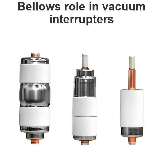
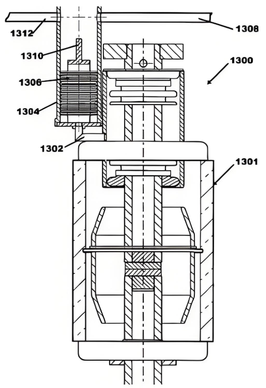
The primary approach to mechanical pressure monitoring involves attaching an additional movable component to the VI using a bellows or similar mechanism (refer to Figure 1). When the vacuum is completely lost, this additional part moves due to the equalization of internal and external pressures. Unlike the moving contact, which is constrained by the circuit breaker mechanism, this additional part is free to move. A detection system monitors the position changes of this additional component and reacts accordingly. Depending on the detection system used, this setup allows for continuous monitoring of the VI. The motion of the additional part is determined by its own design rather than the overall VI design, making this method applicable to low, medium, and high-voltage VIs.
Practical Considerations
While theoretically possible, using the closing force on the VI's moving terminal to detect vacuum loss presents challenges. Atmospheric pressure normally applies a force of several hundred newtons to the VI’s moving terminal, whereas the circuit breaker itself applies a closing force of several thousand newtons. Therefore, identifying a reduction in the VI’s closing force through the breaker's mechanical behavior is difficult due to the relatively small magnitude of the VI closing force compared to that of the circuit breaker. In vacuum contactors, however, where the applied force from the contactor mechanism is lower, diagnosing complete vacuum loss through mechanical behavior may be more feasible.
By employing an additional moving part and a detection system, mechanical pressure monitoring offers a practical solution for continuously assessing the vacuum condition of VIs. This technique provides a reliable means to detect total vacuum loss, although it cannot identify partial pressure increases within the VI. Nonetheless, it represents a valuable tool for ensuring the integrity and functionality of VIs across various voltage levels and applications.
This method ensures that any significant vacuum loss is promptly detected, allowing for timely maintenance or replacement actions, thereby enhancing the reliability and safety of electrical systems relying on VIs.
 Background on Vacuum Interrupter Monitoring Using Mechanical Pressure Monitoring Method
The mechanical pressure monitoring technique assesses the vacuum integrity of a Vacuum Interrupter (VI) by detecting changes in mechanical behavior due to the loss of closing force caused by atmospheric pressure on the moving terminal. This method provides a binary, pass/fail measurement indicating whether the VI has lost its vacuum and is "up-to-air." Pressures around the Paschen minimum and other critical points where VI performance begins to degrade are too low to cause any detectable mechanical change using this method.
Advantages and Disadvantages of the Mechanical Pressure Monitoring Method
Advantages:
• Compatibility: The method is generally compatible with various insulation types, including SF6, oil, and solid insulation, provided that practical issues such as space constraints and guiding light to detection equipment can be managed.
• Optical Technique Benefits: Utilizing an optical technique allows for relocating non-optical components into the low-voltage compartment of the switchgear, which can enhance safety and ease of maintenance.
Disadvantages:
• Installation Requirement: The moving part necessary for pressure monitoring must be installed during the initial manufacturing of the VI. It cannot be retrofitted to already built VIs. While it might be theoretically possible to integrate VIs equipped with this feature into existing circuit breakers along with the required monitoring equipment, practical challenges related to fitting the extension for the extra part into existing installations often make this impractical.
• Reliability Concerns: The reliability of the measurement equipment compared to the VI itself poses a significant risk. Additional brazed parts added to the VI introduce potential new leak paths and may be more susceptible to damage during installation, potentially leading to vacuum loss.
Fragility of Components:
- Optical Techniques: Fiber optics used in the detection system are vulnerable to misalignment, damage during installation, and blockages from condensation or dust.
- Electrical Contact Method: Motion detection via electrical contacts requires a powered microcircuit near the VI, which must also be electrically isolated. This introduces several potential failure modes, including issues with microcircuit reliability, successful signal transmission, powering the circuit, and maintaining electrical isolation.
In summary, while the mechanical pressure monitoring method offers a straightforward way to confirm if a VI has completely lost its vacuum, it comes with notable limitations. These include the inability to retrofit existing VIs, potential reliability concerns with additional components, and practical challenges related to installation and operation. Careful consideration of these factors is essential when deciding on the suitability of this method for specific applications. Ensuring robust design and implementation can help mitigate some of these risks, thereby enhancing the overall reliability and effectiveness of vacuum interrupter monitoring systems.