Bellows role in vacuum interrupters

The mechanical life of vacuum interrupters is significantly influenced by several critical contact motion parameters:
- Steady - state contact stroke or gap: This determines the distance the contacts separate during operation, impacting the electrical insulation and arc - extinguishing capabilities.
- Opening and closing speed: Faster speeds can enhance the switching performance but also impose greater dynamic loads on the components, including the bellows.
- Motion damping at the end of opening and closing stroke: Adequate damping is essential to minimize vibrations and reduce mechanical stress on the bellows and other parts.
- Overshoot and rebound on opening: These phenomena can cause additional wear and tear on the contacts and the bellows, potentially shortening the overall lifespan.
- Mounting resilience: The way the vacuum interrupter is mounted can affect the distribution of forces during operation, influencing the mechanical life of the bellows.
- Contact bouncing on closing: Excessive contact bouncing can lead to arcing and increased stress on the bellows, degrading its performance over time.
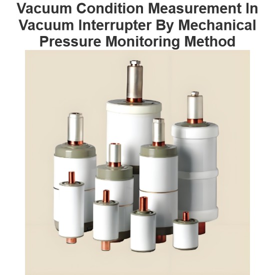
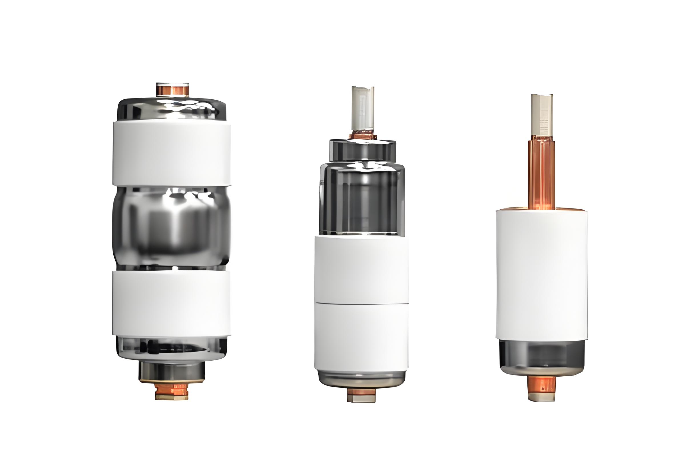
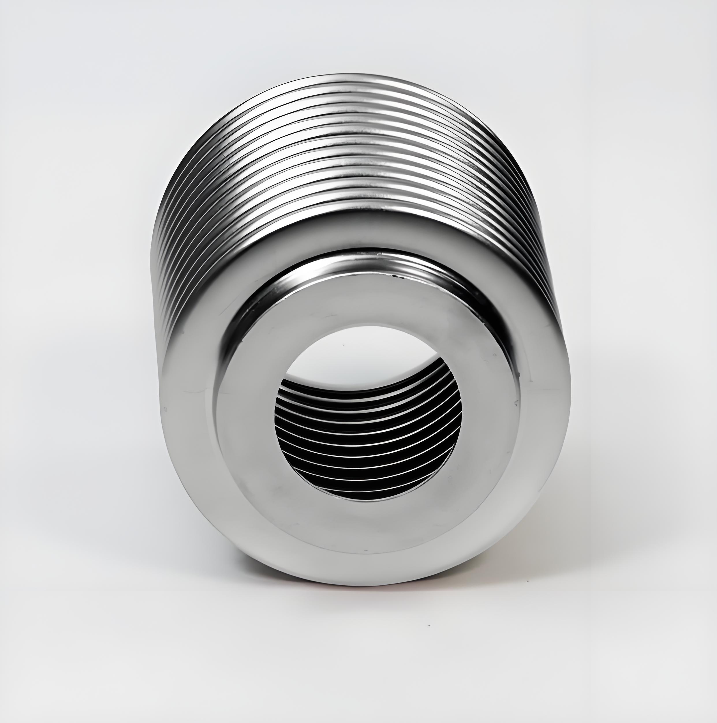
The bellows play a dual - role in vacuum interrupters. They enable the movement of the moving contact while maintaining a vacuum - tight seal. Constructed from stainless steel, typically with a thickness of approximately 150 µm, they are engineered to withstand the harsh operating conditions within the interrupter. Three types of bellows have been successfully integrated into vacuum interrupter designs:
- Seamless hydroformed bellows: These are formed without visible seams, potentially offering enhanced integrity and performance.
- Seam - welded hydroformed bellows: Manufactured by welding seams after hydroforming, they balance cost and performance requirements.
- Bellows made from edge - welded, thin stainless - steel washers: Constructed by welding thin washers together, they provide a cost - effective solution for certain applications.
Comprehensive details regarding bellows design and performance can be found in the EJMA Standards.
One end of the bellows is securely fixed by brazing it to the end plate of the vacuum interrupter, while the other end is brazed to the moving terminal and moves in tandem with it as the contacts open and close. In a vacuum interrupter, the bellows are subjected to impulsive motion during contact operations. The opening speed of the moving contact can rapidly increase from 0 m/s to as high as 2 m/s in less than 100 µs. At the end of the contact stroke, whether opening or closing, the moving end of the bellows comes to an abrupt stop
The frequency of these open - close operations varies depending on the duty cycle. In some cases, they can occur numerous times, while in others, they are rare. The motion imparted to the bellows is far from uniform, and it is common for the bellows to oscillate multiple times during a single opening or closing operation. For those interested in analyzing this bellows motion, a general analytical approach has been developed to determine the dynamic stresses experienced by the bellows under impulsive motion.
Most vacuum interrupter manufacturers source their bellows from well - established bellows manufacturers and collaborate with them to achieve the desired bellows lifespan. This is typically accomplished by incorporating the bellows into a practical vacuum interrupter and conducting mechanical life tests on a statistically significant number of vacuum interrupter samples. A specified mechanical life can then be assigned to the vacuum interrupter with that bellows using Weibull analysis. Usually, the mechanical life limit of a vacuum interrupter is determined by the number of operations the bellows can endure before fatigue failure occurs.
When mechanically testing a vacuum interrupter, it is crucial to subject the bellows to the same operating parameters it will encounter in a switching device. These parameters include the total travel (operating gap plus over - travel), maximum opening speed, maximum closing speed, and the effects of acceleration and deceleration. Testing the bellows within the vacuum interrupter ensures that it undergoes all the manufacturing steps that the finished device will experience. For instance, it should be exposed to all the heating and cooling cycles required for vacuum interrupter manufacturing. These processes will inevitably anneal the metal of the bellows, altering its granular microstructure and, consequently, its performance characteristics.
The mechanical life of a specific bellows depends not only on the above - mentioned operating parameters but also on its own physical attributes. These include the type of stainless steel used, its length, diameter, thickness, the number of convolutions, and its ability to dampen motion once the contact stops moving. It is feasible to design bellows that can reliably perform the normal 30,000 operations required for most vacuum circuit breakers and vacuum reclosers, and even exceed 10^6 operations for vacuum contactors. However, despite vacuum interrupter manufacturers' efforts to design their products to meet the specified mechanical life of various switching devices, most vacuum interrupters do not reach their stated mechanical life when deployed in the field.For more insights into the failure reasons of Vacuum Interrupters (VIs), please refer to the relevant article.
The vacuum interrupter designer must take precautions to prevent the user from twisting the bellows when installing the vacuum interrupter into a mechanism. A twisted bellows can have its mechanical life severely reduced, potentially to less than 1% of its designed lifespan. The torque that can be applied to the thin - walled bellows in a vacuum interrupter before permanent twisting is relatively low, approximately 8.5–11.5 Nm. To avoid bellows twisting, the designer should insert an anti - twisting bushing into it. This bushing can be locked in place by attaching it to the end plate of the interrupter. The inner surface of the bushing is shaped or features a keyway to prevent any rotation of the moving copper terminal attached to the bellows (as shown in Figure 2). The bushing material can be metal or a plastic such as Nylatron. When using plastic materials like Nylatron and Valox, caution is necessary. These materials can only be used in applications where the maximum permissible temperature they will experience is limited. For example, for Nylatron, the temperature at which its tensional strength is reduced to 50% after 100,000 hours is approximately 125°C (it can withstand higher temperatures for short periods without deforming due to its glass fiber content), and for Valox DR48, it is around 140°C. There are also more expensive, higher - temperature plastics available, such as “Ultem 2310 R.”