Vacuum Circuit Breakers Testing Methods


When vacuum interrupters are manufactured or used in the field, there are three tests used to validate their functionality: 1. Contact Resistance Test; 2. High Potential Withstand Test; 3. Leak-rate Test.
Contact Resistance Test
- During the contact resistance test, a micro-ohmmeter is applied to the closed contacts of the vacuum interrupter (VI), and the resistance is measured and recorded. The result is then compared against the design specifications and/or the average values for other vacuum interrupters from the same production run.
- This testing method ensures that the contact resistance of each vacuum interrupter meets the expected technical specifications, thereby guaranteeing its performance and reliability. By comparing the results with the average values of the same batch, potential anomalies can be identified, allowing for timely corrective actions to be taken.
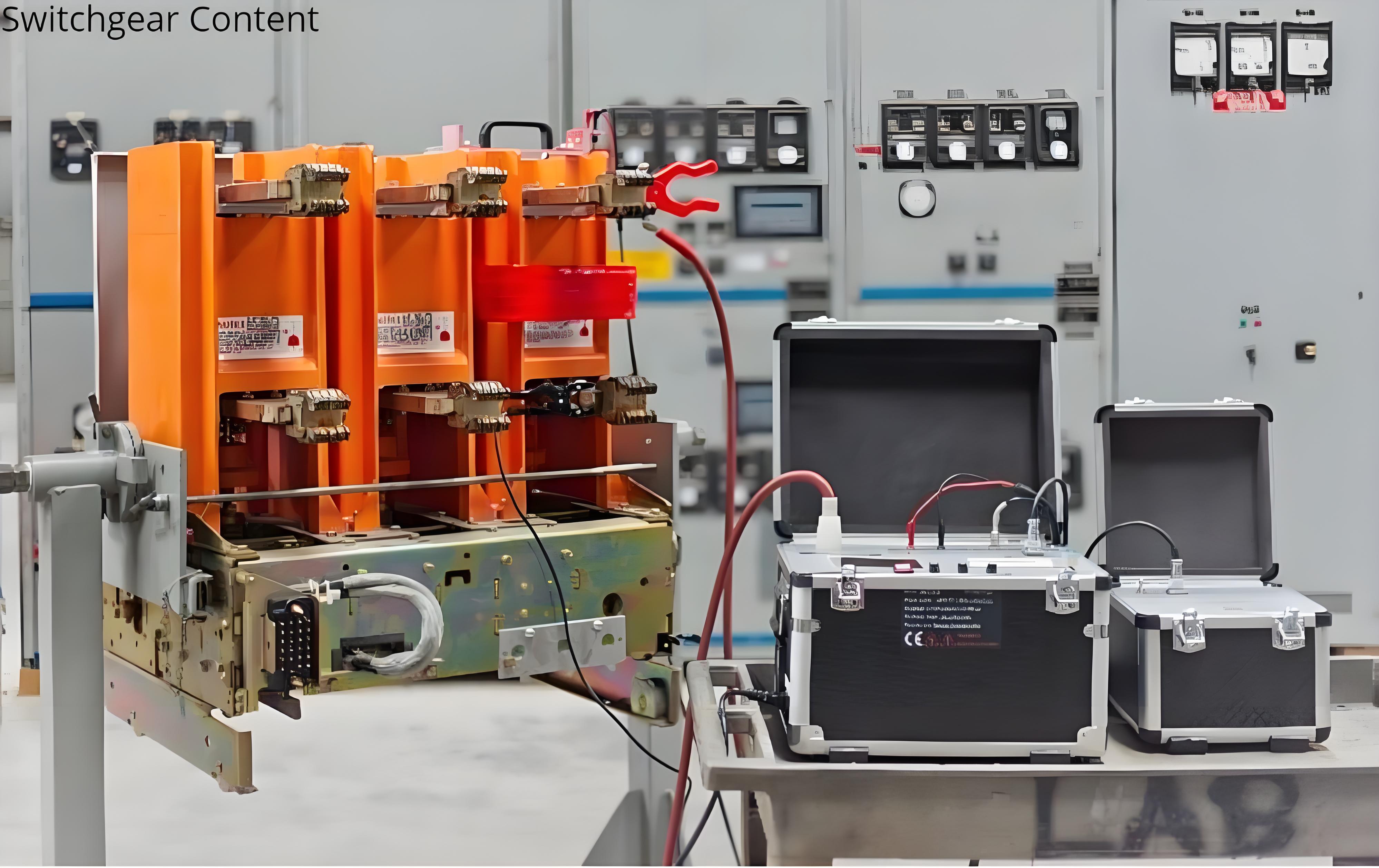
High Potential Withstand Test
In the high potential withstand test, a high voltage is applied across the open contacts of the vacuum interrupter (VI). The voltage is gradually increased to the test value, and any leakage current is measured. Factory testing can be performed using either AC or DC high-potential test sets. Manufacturers offer various portable test sets for performing high-potential tests on open vacuum interrupters. Most of these test sets are DC test sets because they are considerably more compact and thus more portable than AC high-potential test sets.
When using a DC test voltage, a high field emission current from a microscopic sharp spot on one contact can be misinterpreted as an indication that the vacuum interrupter is filled with air. To avoid such misinterpretation, the vacuum interrupter should always be tested under both positive and negative DC voltage polarities. This means the test should be conducted by reversing the polarities. A defective interrupter filled with air will exhibit similarly high leakage currents in both polarities.
A good interrupter with a proper vacuum level might still show high leakage current, but this is generally only in one polarity. An interrupter with a tiny sharp spot on the contact produces a high field emission current only when it acts as a cathode, not an anode. Therefore, repeating the test by reversing the polarities will prevent any misinterpretation of the results. The test voltage to be used for testing a vacuum interrupter should follow the recommendations of the vacuum interrupter manufacturers.
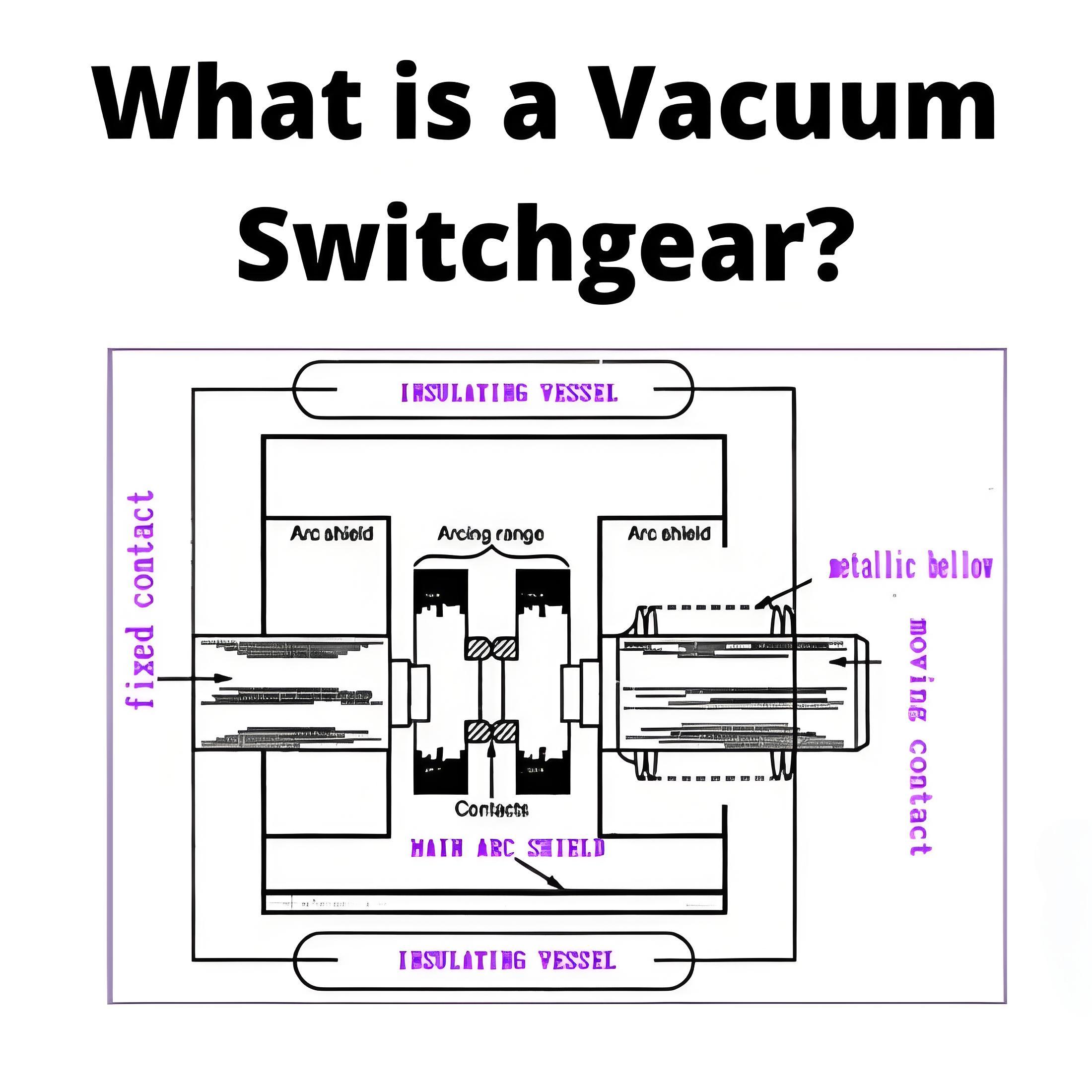
Below is an example of a high-voltage vacuum interrupter tester, ranging from 10 to 60 kV DC, provided by Megger company:
Leak Rate Test (MAC Test)
The leak rate test is based on the Penning Discharge Principle, named after Frans Michael Penning (1894-1953). Penning demonstrated that when a high voltage is applied to open contacts in a gas and the contact structure is surrounded by a magnetic field, the amount of current flowing between the plates is a function of the gas pressure, the applied voltage, and the magnetic field strength.
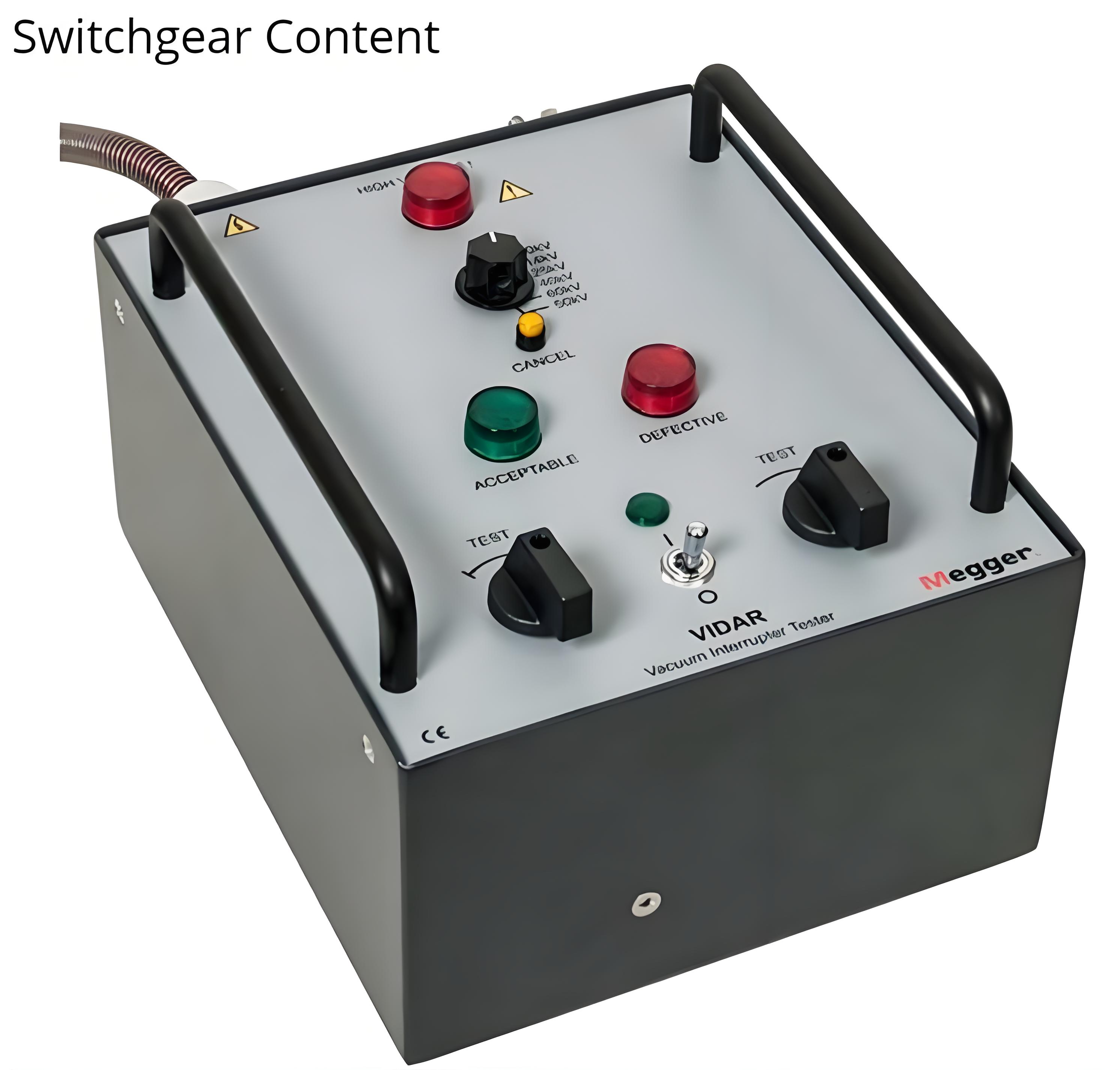
Basic Test Setup
The figure below illustrates the basic setup for a vacuum interrupter (VI) leak rate test. For field testing, the VI is placed inside a portable fixed magnetic coil, or a flexible cable is wrapped around the test specimen a specified number of times. When the test begins, high-voltage DC is applied to the VI, and the baseline leakage current is measured. Next, during a second application of high-voltage DC, a DC voltage pulse is applied to the magnetic field coil, and the total current is measured during this pulse. The ion current is calculated as the total current minus the leakage current. Since both the magnetic field strength and the applied voltage are known, the only remaining variable is the gas pressure. If the relationship between gas pressure and current flow is known, the internal pressure can be calculated based on the measured current.
This testing method allows for precise assessment of the vacuum level within the vacuum interrupter, ensuring its performance and reliability. By comparing changes in current under different conditions, potential leakage issues can be effectively detected, ensuring the safe operation of the equipment.
Even the best vacuum interrupters (VIs) will have some level of leakage, and this leakage may be slow enough that the VI meets or even exceeds the manufacturer’s predicted service life. However, unexpected increases in the leak rate can significantly shorten the VI's lifespan. When VIs within circuit breakers are tested during routine maintenance using traditional methods, they return to service with only the assurance that they will function at that moment, offering no forecast about future performance.
Advantages of Leak Rate Testing
Setting up and performing the leak rate test is no more difficult than many of the field tests that maintenance personnel are already familiar with, and the results are extremely accurate in determining the internal pressure of the VI. With the continued adoption of leak rate testing, the electrical industry can expect to see a marked improvement in maintenance efficiency and a reduction in the number of unexpected failures of VIs.
By adopting leak rate testing, not only can the current functionality of the equipment be ensured, but it also provides crucial predictive data about future performance. This approach not only helps extend the lifespan of the equipment but also aids in developing more effective preventive maintenance plans, thereby enhancing the overall reliability and safety of the system.
The above description has been refined to clearly and accurately convey the information while enhancing readability. It highlights the importance of leak rate testing and its advantages over traditional testing methods, pointing out the potential positive impacts on the electrical industry.
Using the Rigid Magnetic Coil in MAC Test on the Entire Pole
The figure above shows how the rigid magnetic coil used in the MAC test can be applied to the entire pole when the vacuum interrupter (VI) is not readily accessible. While many of the medium-voltage vacuum circuit breakers in the field allow for the application of the coil to either individual VIs or individual poles, some do not have sufficient space or configuration to accommodate this.