Search
Español
English
Español
Français
العربية
Русский
Português
हिन्दी
বাংলা
Deutsch
日本語
Bahasa Indonesia
Italiano
RFQ
Home
Market
Solutions
Knowledge
Download the app
MENU
Home
Market
Solutions
Knowledge
Español
English
Español
Français
العربية
Русский
Português
हिन्दी
বাংলা
Deutsch
日本語
Bahasa Indonesia
Italiano
Home
Knowledge
Circuit Theory
Topics
Power Systems
Power system
Machines
circuit diagram
Measurement
Basic Electrical
Basic
Industrial circuit
Basic knowledge
Transmission
Electric Power Knowledge
Control
Motor
Transformer
Electric Motors
Protection
household circuit
Generation
Control Circuit
Switchgear
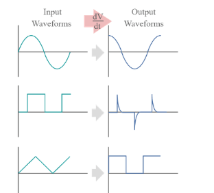
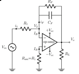
Op Amp Differentiator
Differentiator is an op amp based circuit, whose output signal is proportional to differentiation of input signal.An op amp differentiator is basically an inverting amplifier with a capacitor of suitable value at its input terminal. The figure below shows the basic circuit diagram of an op amp differentiator.We will first assume that the op amp used here is an ideal op amp. We know that the voltage at both inverting and non inverting terminals of an ideal op amp is same. As the electric potentia
Electrical4u
03/13/2024
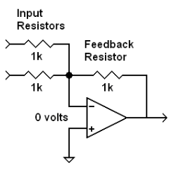
Summing Amplifier or Op Amp Adder
An op amp is an amplifier. But an op amp can also perform summing operation. We can design an op amp circuit to combine number of input signals and to produce single output as a weighted sum of input signals.Summing amplifier is basically an op amp circuit that can combine numbers of input signal to a single output that is the weighted sum of the applied inputs.The summing Amplifier is one variation of inverting amplifier. In inverting amplifier there is only one voltage signal applied to the in
Electrical4u
03/13/2024
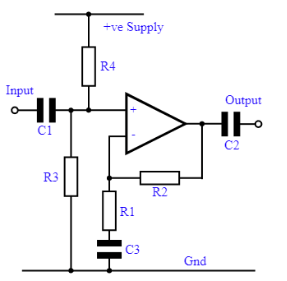
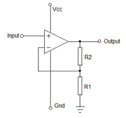
Non Inverting Operational Amplifier (OP Amp): Formula & Gain
Non-inverting amplifier is an op-amp-based amplifier with positive voltage gain.A non-inverting operational amplifier or non-inverting op-amp uses an op-amp as the main element.The op amp has two input terminals (pins). One is inverting denoted with a minus sign (-), and other is non-inverting denoted with a positive sign (+).When we apply any signal to the non – inverting input, it does not change its polarity when it gets amplified at the output terminal.So, in that case, the gain of the ampli
Electrical4u
03/13/2024
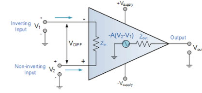
Ideal Operational Amplifier or Ideal O Amp
What is an Ideal OP Amp?An operational amplifier (OP Amp) is a direct current coupled voltage amplifier. That is, it increases the input voltage that passes through it. The input resistance of an OP amp should be high whereas the output resistance should be low. An OP amp should also have very high open loop gain. In an ideal OP amp, the input resistance and open loop gain is infinity whereas the output resistance is zero.An ideal OP amp has have following characteristics— Characteristic
Electrical4u
03/13/2024
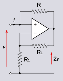
Negative Feedback in Op amp and Closed Loop Gain of Op amp
Negative Feedback in Op AmpWe obtain Negative feedback in an op amp by connecting output terminal of an op amp to its inverting input terminal through a suitable resistance as shown below.The gain of an op amp with negative feedback is called closed loop gain.Closed Loop Gain of Op AmpWhen we connect a feedback resistance and a resistance in series with the inverting input terminal of an op-amp as shown in the above picture, the gain of the system just becomes the negative ratio of feedback resi
Electrical4u
03/13/2024
Op amp or Operational Amplifier
Anoperational amplifierorop ampis a DC coupled voltage amplifier with a very high voltage gain.Op amp is basically a multistage amplifier in which a number of amplifier stages are interconnected to each other in a very complicated manner. Its internal circuit consists of many transistors, FETs and resistors. All this occupies a very little space.So, it is packed in a small package and is available in the Integrated Circuit (IC) form. The term Op Amp is used to denote an amplifier which can be co
Electrical4u
03/13/2024
Applications of Op Amp
A linear amplifier like an op amp has many different applications. It has a high open loop gain, high input impedance and low output impedance. It has high common mode rejection ratio. Due to these favourable characteristics, it is used for different application. In this article, we are discussing some of the most prominent uses of an Op amp. This is not an exhaustive list but covers the important applications of op amp within the scope of our discussion.Op Amp applications as Inverting Amplifie
Electrical4u
03/13/2024
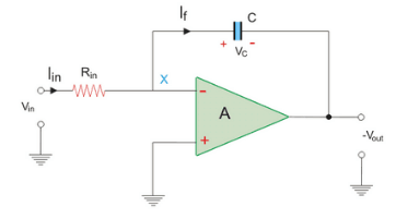
Op-Amp Integrator: A Circuit that Performs Mathematical Integration
What is an Op-Amp Integrator?An op-amp integrator is a circuit that uses an operational amplifier (op-amp) and a capacitor to perform the mathematical operation of integration. Integration is the process of finding the area under a curve or function over time. An op-amp integrator produces an output voltage that is proportional to the negative integral of the input voltage, meaning that the output voltage changes according to the duration and amplitude of the input voltage.An op-amp integrator c
Electrical4u
03/13/2024
RL Parallel Circuit
In RL parallel circuitresistor and inductor are connected in parallel with each other and this combination is supplied by a voltage source, Vin. The output voltage of circuit is Vout. Since the resistor and inductor are connected in parallel, the input voltage is equal to output voltage but the currents flowing in resistor and inductor are different.The parallel RL circuit is not used as filter for voltages because in this circuit, the output voltage is equal to input voltage and for this reason
Electrical4u
03/13/2024
RL Circuit Transfer Function Time Constant RL Circuit as Filter
The resistor and inductor are the most fundamental linear (element having linear relationship between voltage and current) and passive (which consume energy) elements. When resistor and inductor are connected across voltage supply, the circuit so obtained is called RL circuit.Types of RL Circuit RL Series Circuit-Whenresistanceand inductor are connected in series with voltage supply. The circuit is calledseries RL circuit. RL Parallel Circuit-When resistance and inductor are connected in paralle
Electrical4u
03/13/2024
1
2
3
4
5
6
7
8
9
Source professional electrical partners, experts, and explore smart grid & energy solutions.
Inquiry
Send Now
Download
Experts Electrical is dedicated to serving the personnel in the global power industry.
Join Experts Electrical, not only can you discover power equipment and power knowledge, but also canhnd like - minded friends!