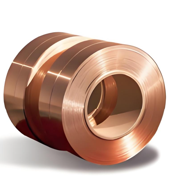
| Brand | Wone |
| Model NO. | Customized Copper-aluminum Composite Strip/Bar/Plate EXW/FOB/CIF |
| Thickness | 2.24-50mm |
| Width | 16-400mm |
| Series | TM&TMY |
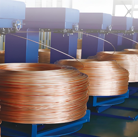
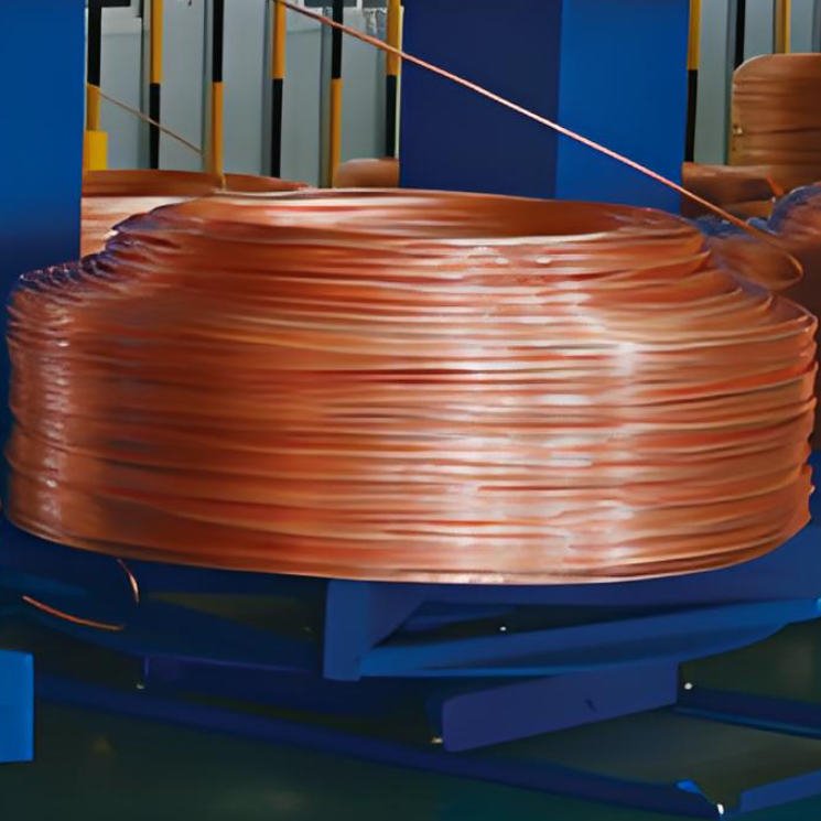
Product application
Product application: Apply to electrical engineering like high/low voltage clectrical appliances, switch contact, power distribution equipment, bus duct and larg current electrolysis refining project like mental smelting petrochemical.
Operative Norm
GB/T5585.1-2005 Electrical copper busbar.
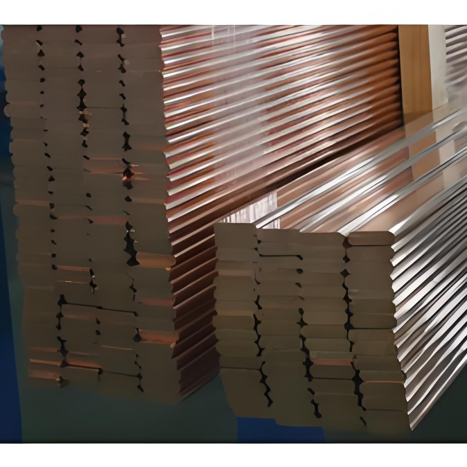
Type and Chemical composition

Section shapes of copper busbar: circular bead, round edge, all round edge.

a-Thickness is the narrow side dimension mm; b-Thickness is width dimension mm; r -Rounded Corenur Rounded edge radius mm.
Thickness deviation

Width deviation
Physical property

Q: What kind of material is copper bus?
A: Copper busbar is a high-current conductive product made of copper. It is usually rectangular or circular long strip, with high purity copper material, copper conductivity is good, which makes the copper bus can carry a large current.
Q: Where is the copper bus mainly used?
A: It is widely used in power facilities such as substations and distribution rooms. For example, in substations, it is used to connect transformers, switchgear and other equipment, which can effectively distribute and transmit electric energy. It is also indispensable in the electrical system of large factories, which can distribute electrical energy to various workshops or large equipment.
Q: What are the advantages of copper bus bars?
A: It has many advantages, first of all, strong conductivity, can reduce power loss. Secondly, its mechanical strength is relatively high, and it can withstand certain mechanical stresses. Moreover, the processing performance of the copper busbar is good, and the processing operations such as cutting and bending can be carried out according to the actual needs.