• The Voltage Tester 6V-400V Electricians And DIYers To Measure AC/DC Voltage
  • The Voltage Tester 6V-400V Electricians And DIYers To Measure AC/DC Voltage
  • The Voltage Tester 6V-400V Electricians And DIYers To Measure AC/DC Voltage
  • The Voltage Tester 6V-400V Electricians And DIYers To Measure AC/DC Voltage
The Voltage Tester 6V-400V Electricians And DIYers To Measure AC/DC Voltage
$11.00
Model
MDT-400DP
MDT-230DP
MDT-120DP
MDT-50DP
MDT-24DP
MDT-12DP
Basic info
Brand Wone
Model NO. UT22B-EU Voltage Tester 6V-400V Electricians And DIYers To Measure AC/DC Voltage
Frequency range 50/60Hz
Voltage range 280V~400V
Series MDT 22B-EU
Product Detail

Description

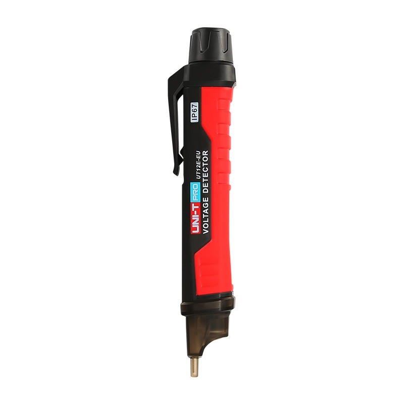
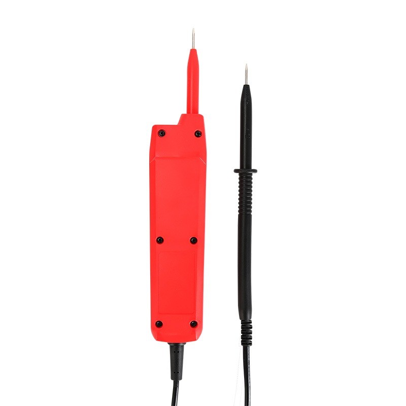
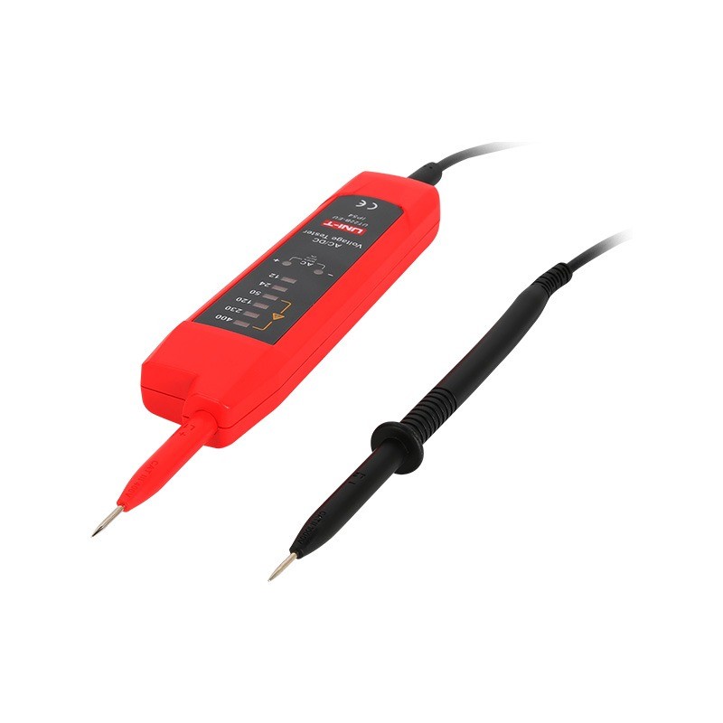
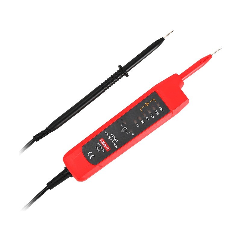
The UT22B-EU voltage tester is a simple to use tool for electricians and DIYers to measure AC/DC voltage. This voltage tester is IP54 rated, and designed to withstand a 2-meter drop. The great thing about this product is that it does not require any battery, its power is supplied by the voltage being tested! UT22B can automatically distinguish between AC and DC voltage, indicated by the number of LED lights.

Feature

 Certifications: CE, UKCA

  •  Automatically detect AC/DC voltage

  •  Automatically indicate DC polarity (+/-)

  •  Hazardous voltage indicator when voltage >50V

  •  Auto detection of AC/DC

  •  Input protection

Specifications


image.png

image.png

image.png

How the input protection circuitry in the voltage tester is protected?

  • Overcurrent Protection: When the input current exceeds the rated value of the fuse or current-limiting resistor, the fuse will blow or the current-limiting resistor will restrict the current, preventing damage to the tester from overcurrent.

  • Overvoltage Protection: Clamping diodes and Transient Voltage Suppression (TVS) diodes can quickly conduct when the voltage exceeds a certain threshold, absorbing or diverting excess voltage energy to protect the internal circuitry from damage.

  • Electrical Isolation: An isolation transformer can electrically isolate the input signal from the internal circuitry of the tester, preventing high voltage from directly entering the tester, causing damage or posing a threat to personal safety.

  • Filtering: Capacitors can filter out high-frequency noise from the input signal, preventing this noise from interfering with the normal operation of the tester.

  • Comprehensive Protection: Input protection circuits typically employ a combination of the above components and technologies, forming a multi-layered protection mechanism to ensure that the tester can operate safely under various adverse conditions.


Know your supplier
Wone
Main Categories
High voltage/Low voltage/Wire cable/Instrument meters/New energy/Tester/Production equipment/Generator/Electrical fittings/Integrated Electrical Equipment
Business Type
Design/Manufacture/Sales
Highest Annual Export (USD)
$50,000,000
Professional Experience
1 years
Workplace
65666m²m²
占位
占位
Related Products
Related Knowledges
Failure Analysis and Design Optimization of Conventional Grounding Transformers
I. Core Cause of Damage: Electrodynamic Impact (Complying with GB/T 1094.5 / IEC 60076-5)The direct cause of high-voltage winding end collapse is the instantaneous electrodynamic impact induced by short-circuit current. When a single-phase grounding fault occurs in the system (such as lightning overvoltage, insulation breakdown, etc.), the grounding transformer, as the fault current path, withstands high-amplitude and steep-rise-rate short-circuit currents. According to Ampère's force law
Felix Spark
06/12/2025
Analysis of Grounding Transformer Operational Behavior Under System Single-Phase-to-Ground Fault Conditions
1 Theoretical AnalysisIn distribution networks, grounding transformers serve two key roles: powering low - voltage loads and connecting arc - suppression coils at neutrals for grounding protection. Grounding faults, the most common distribution network fault, heavily impact transformers’ operating characteristics, causing sharp changes in electromagnetic parameters and status.To study transformers’ dynamic behaviors under single - phase grounding faults, build this model: Assume a tr
Felix Spark
06/12/2025
Design Calculations for Neutral Grounding Schemes and Grounding Transformer Sizing in Utility-Scale Solar PV Plants
1 Classification of Neutral Grounding Methods for Solar Photovoltaic Power StationsInfluenced by differences in voltage levels and grid structures across regions, the neutral grounding methods of power systems are mainly categorized into non-effective grounding and effective grounding. Non-effective grounding includes neutral grounding via arc suppression coils and neutral ungrounded systems, while effective grounding comprises neutral solid grounding and neutral grounding via resistors. The sel
Dyson
06/12/2025
Zero-Sequence Impedance Characterization of Dry-Type Grounding Transformer with ZN Connection
In a neutral-insulated three-phase power system, an earthing transformer provides an artificial neutral point, which can be solidly earthed or earthed via reactors/arc suppression coils. The ZNyn11 connection is typical, where zero-sequence magnetomotive forces in the inner/outer half-windings of the same core column cancel out, balancing fault currents in series windings and minimizing zero-sequence leakage flux/impedance.Zero-sequence impedance is critical: it determines fault current magnitud
Dyson
06/12/2025
Case Analysis on Maloperation of Grounding Transformer Overcurrent Protection Relay
The neutral grounding mode refers to the connection between the power system neutral point and ground. In China's 35 kV and below systems, common methods include ungrounded neutral, arc-suppression coil grounding, and small-resistance grounding. The ungrounded mode is widely used as it allows short-term operation during single-phase grounding faults, while small-resistance grounding has become mainstream for its fast fault removal and overvoltage limitation. Many substations install grounding tr
Felix Spark
06/12/2025
Discussion on the Design of Low Zero-Sequence Impedance Grounding Transformers
With the expansion of power system scale and the cableization process of urban power grids, the capacitive current in 6kV/10kV/35kV power grids has significantly increased (generally exceeding 10A). As power grids at this voltage level mostly adopt neutral ungrounded operation mode, and the distribution voltage side of main transformers is usually in delta connection, lacking a natural grounding point, the arc during ground faults cannot be reliably extinguished, necessitating the introduction o
Dyson
06/11/2025
×
Inquiry
Download
Experts Electrical is dedicated to serving the personnel in the global power industry.
Join Experts Electrical, not only can you discover power equipment and power knowledge, but also canhnd like - minded friends!
商品视频播放