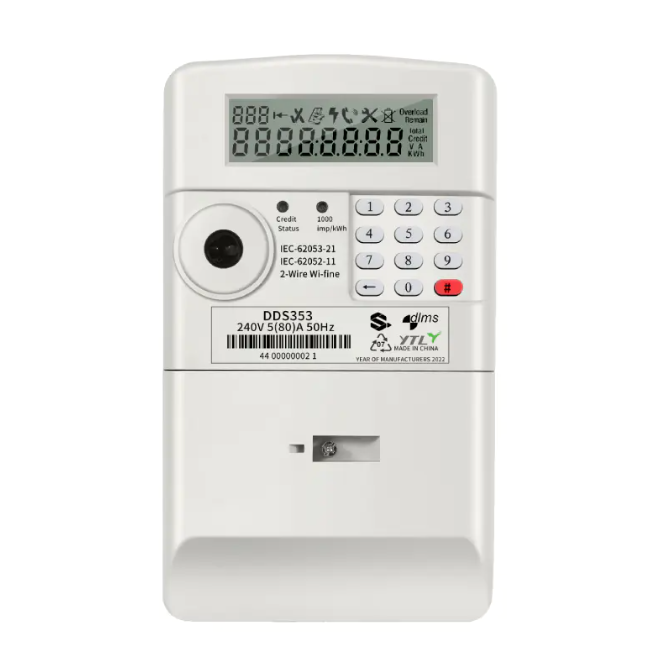
STS Prepaid Wi-Fine Energy Meter Single Phase Wall Mounted ODM
$90.00
Model

| Brand | Wone |
| Model NO. | STS Prepaid Wi-Fine Energy Meter Single Phase Wall Mounted ODM |
| Rated voltage | 230V |
| Rated normal current | 5(30)A |
| Rated frequency | 50(Hz) |
| Methods of Communication | RS485 |
| Series | D123073 |
Description
STS prepaid standard meter is a media-free prepaid meter, which does not need to be recharged with IC card, magnetic card, radio frequency card, etc., and only needs to be recharged by entering the 20-digit code through the keyboard; It can also be used for power recharge, data viewing, and control management through remote communication.
Specifications
| Main |
|
|---|---|
| Range | D123073 |
| Product or Componet Type | Energy meter |
| Country of origin | China |
| Complementary |
|
|---|---|
| Phase | Single Phase |
| Type of measurement | ---- |
| Metering type | Measurement |
| Device Application | Energy Charge |
| Accuracy class | Active power 1.0 |
| Rated Current | 5(80) A |
| Rated Voltage | 230V |
| Network Frequency | 50-60Hz |
| Technology Type | Electronic |
| Display Type | LCD display(LCD 6+2 = 999999.99kWh) |
| Impulse Constant | 1000imp/kWh(LED) 1000imp/kvarh |
| Maximum value measured | 99999.99kWh |
| Tariff input | Tariff |
| Communication port protocol | DLMS |
| Communication port support | RS485 |
| Local signalling | ------ |
| Number of inputs | ------- |
| Number of Outputs | -------------- |
| Output voltage | ---- |
| Mounting Mode | --- |
| Mounting Support | ----- |
| Connections - terminals | ------- |
| Standards | IEC62052-11:2003 IEC62053-21:2003 |
| Environment |
|
|---|---|
| IP degree of protection | IP51 |
| Relative humidity | ≤85% |
| Ambient air temperature for operation | -20…70 °C |
| Ambient Air Temperature for Storage | --20…80 °C |
| Operating altitude | --- |
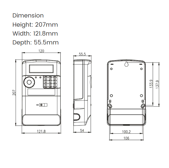
| Dimensions | 55.5mm*121.8mm*207mm |
| Packing Units |
|
|---|---|
| Unit Type of Package 1 | PCE |
| Number of Units in Package 1 | 1 |
| Package 1 Height | 209mm |
| Package 1 Width | 123mm |
| Package 1 Length | 57mm |
| Package 1 Weight | 1.000kg |
Dimensions