• PRJ double winding Copper Strip Foil Winding Machine for machinery industry
  • PRJ double winding Copper Strip Foil Winding Machine for machinery industry
PRJ double winding Copper Strip Foil Winding Machine for machinery industry
$143400.00
Model
PRJ-1600D
PRJ-1600S
PRJ-1400S
PRJ-1400D
PRJ-1200D
PRJ-1200S
PRJ-1000D
PRJ-1000S
PRJ-600D
PRJ-600S
PRJ-800
PRJ-800S
Basic info
Brand Wone
Model NO. PRJ double winding Copper Strip Foil Winding Machine for machinery industry
Outer diameter(mm) 200~600mm
Width material(mm) 250~1600mm
Thickness of foil 0.5-3mm
Winding speed 24.5r/min
Working moment 15000N.M
Total power 63.58KW
Volume Number Double
Series PRJ
Product Detail

Description

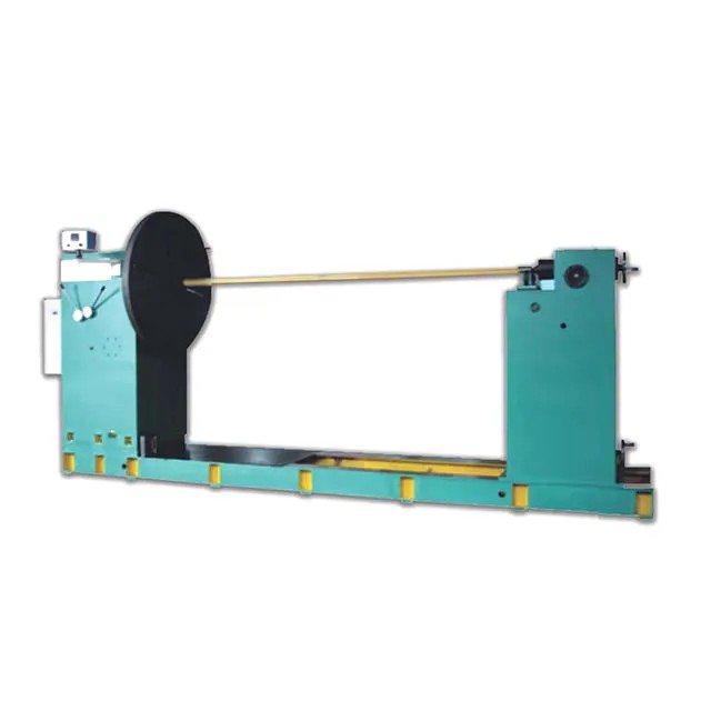
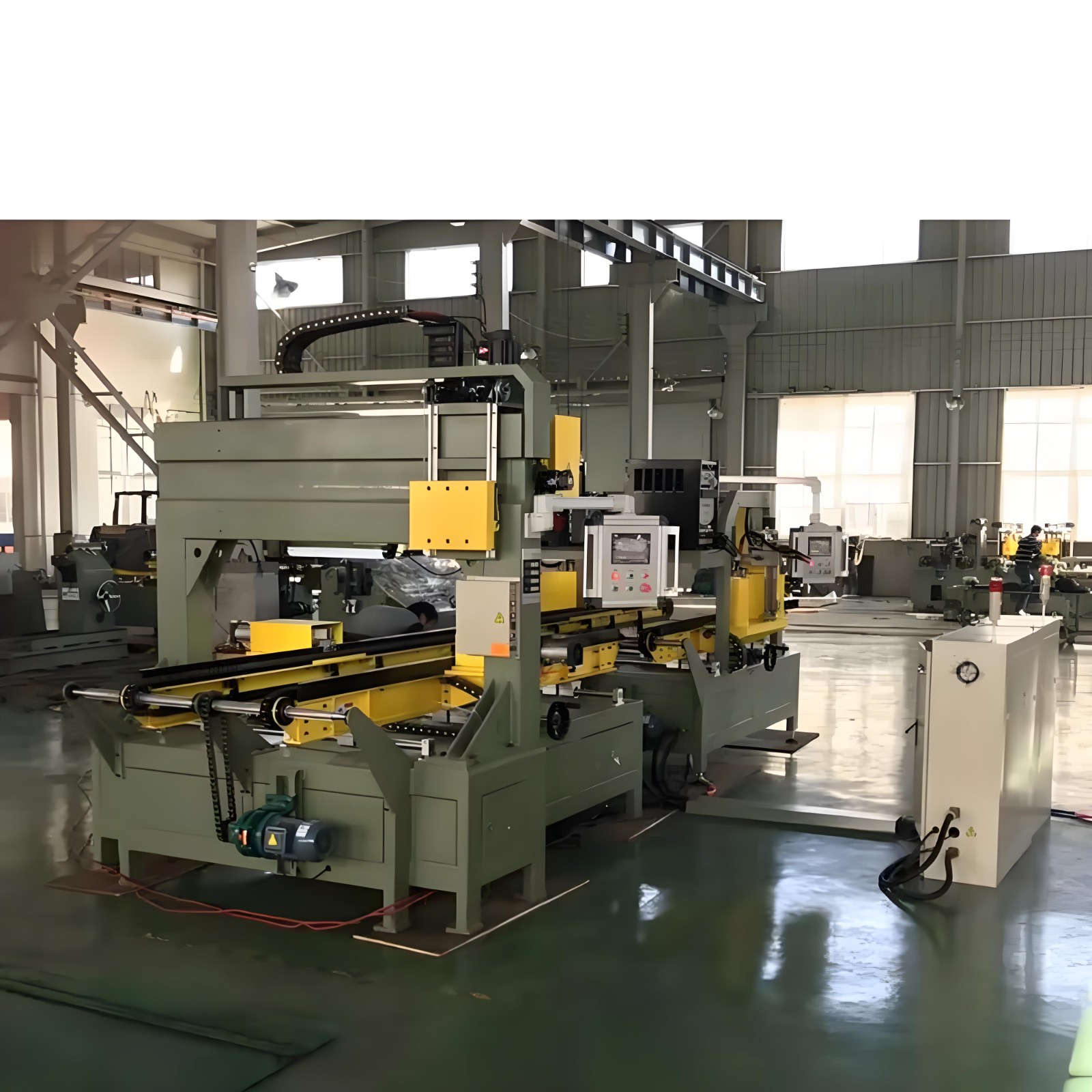
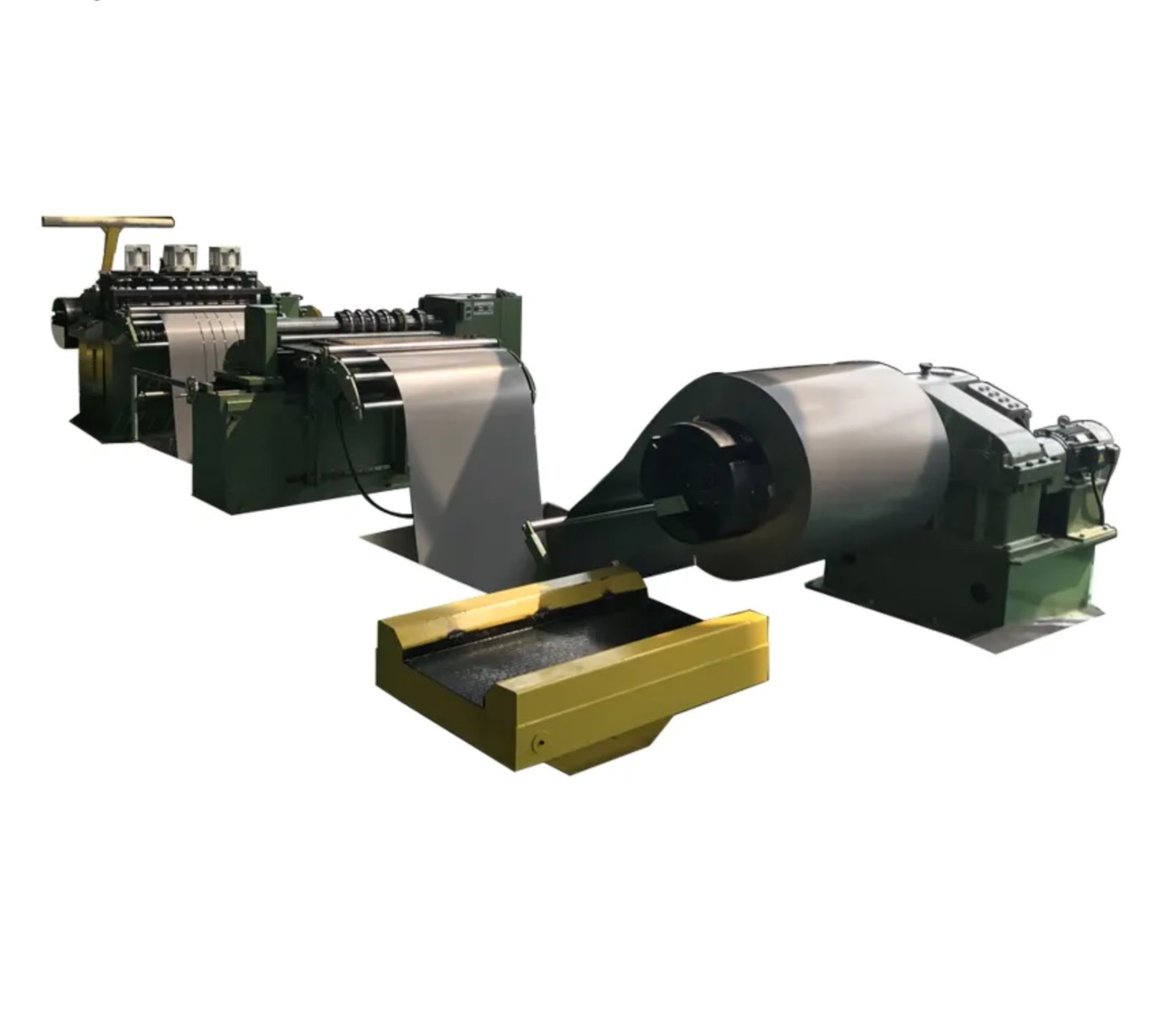
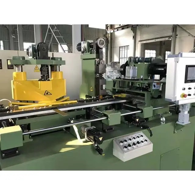
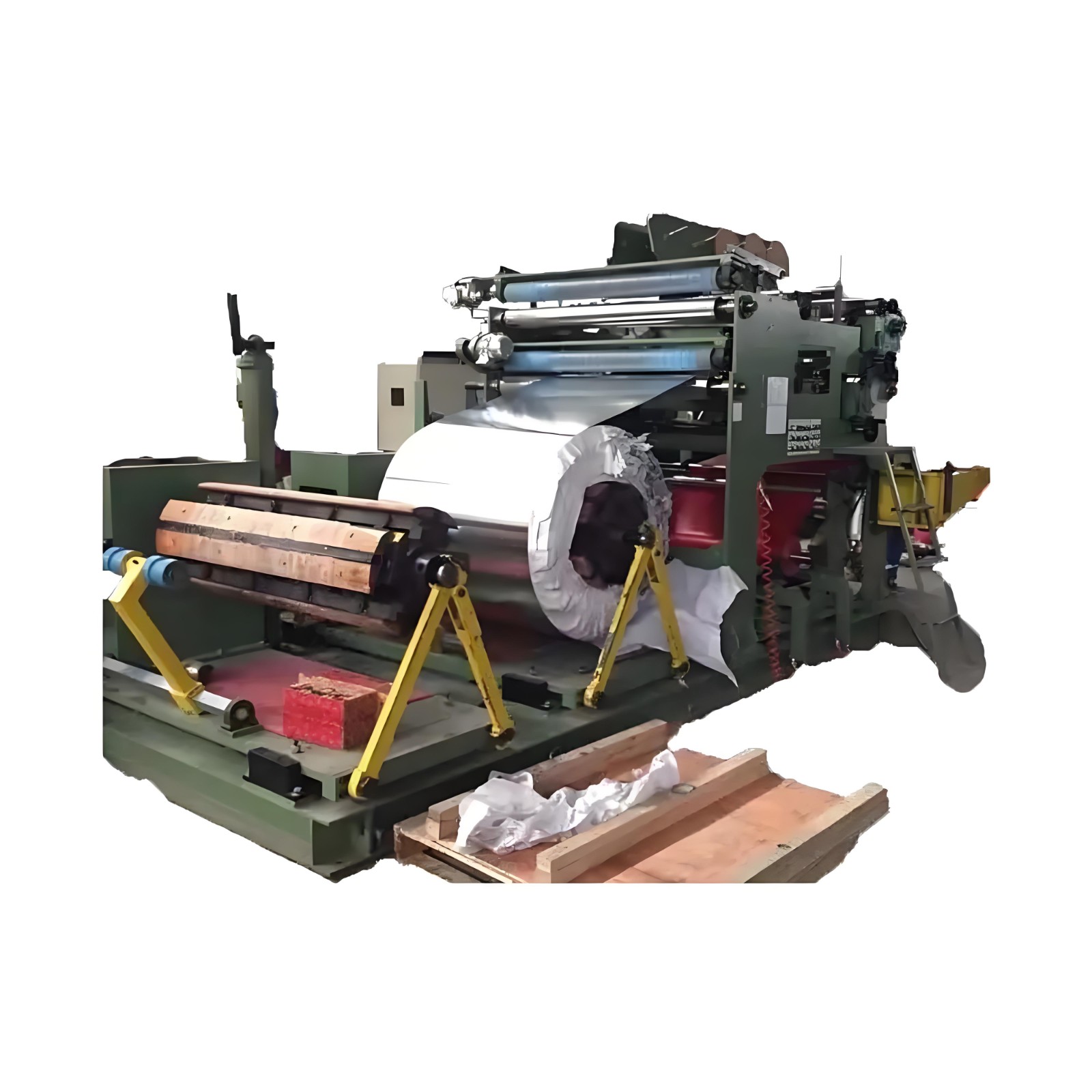
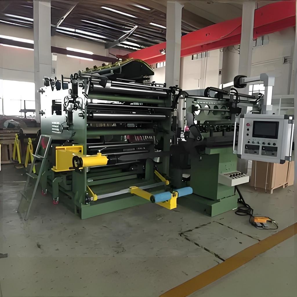
The PRJ Foil Winding Machine is a foil coil winding system which is applicable for transformer and electrical industry. Foil coil is made of copper or aluminum foil of different thickness as conductor, with wide-band insulating material as layer insulation, and narrow-band insulating material as end insulation. The winding is completed by the foil winding machine and the coil is formed. Meanwhile, the welding of the inner and outer leads of the coil and binding of outer surface are completed. Double layer foil winding machine can be used to foil with narrow strips and winding into a wide foil coil or can support a thin foil strip with two  layers of thick foil coil. It can provide enough support to produce foil coil conforming to the requirements of the specification with the functions of the equipment. This machine is a necessary equipment for production of such electrical products.

 Composition

l● De-coiler of foil coil and foil offset regulating system

l● Foil edge burr remover and clean device

l● Foil feeding mechanism 

l● Foil offset regulating sensing system

l● Electrical tensioning device

l● Foil sheet shearing unit 

l● De-coiler for layer insulation 

l● Layer insulation edge cutting mechanism

l● Welding unit

l● Foil winding system 

l● End insulation strip wrapping system 

l● Discharge trolley 

l● Wound coil pressing device

l● Electrical control system

Specifications

1719538795338.jpg

1719538854188.jpg

Know your supplier
Wone
Main Categories
High voltage/Low voltage/Wire cable/Instrument meters/New energy/Tester/Production equipment/Generator/Electrical fittings/Integrated Electrical Equipment
Business Type
Design/Manufacture/Sales
Highest Annual Export (USD)
$50,000,000
Professional Experience
1 years
Workplace
65666m²m²
占位
占位
Related Products
Related Knowledges
Failure Analysis and Design Optimization of Conventional Grounding Transformers
I. Core Cause of Damage: Electrodynamic Impact (Complying with GB/T 1094.5 / IEC 60076-5)The direct cause of high-voltage winding end collapse is the instantaneous electrodynamic impact induced by short-circuit current. When a single-phase grounding fault occurs in the system (such as lightning overvoltage, insulation breakdown, etc.), the grounding transformer, as the fault current path, withstands high-amplitude and steep-rise-rate short-circuit currents. According to Ampère's force law
Felix Spark
06/12/2025
Analysis of Grounding Transformer Operational Behavior Under System Single-Phase-to-Ground Fault Conditions
1 Theoretical AnalysisIn distribution networks, grounding transformers serve two key roles: powering low - voltage loads and connecting arc - suppression coils at neutrals for grounding protection. Grounding faults, the most common distribution network fault, heavily impact transformers’ operating characteristics, causing sharp changes in electromagnetic parameters and status.To study transformers’ dynamic behaviors under single - phase grounding faults, build this model: Assume a tr
Felix Spark
06/12/2025
Design Calculations for Neutral Grounding Schemes and Grounding Transformer Sizing in Utility-Scale Solar PV Plants
1 Classification of Neutral Grounding Methods for Solar Photovoltaic Power StationsInfluenced by differences in voltage levels and grid structures across regions, the neutral grounding methods of power systems are mainly categorized into non-effective grounding and effective grounding. Non-effective grounding includes neutral grounding via arc suppression coils and neutral ungrounded systems, while effective grounding comprises neutral solid grounding and neutral grounding via resistors. The sel
Dyson
06/12/2025
Zero-Sequence Impedance Characterization of Dry-Type Grounding Transformer with ZN Connection
In a neutral-insulated three-phase power system, an earthing transformer provides an artificial neutral point, which can be solidly earthed or earthed via reactors/arc suppression coils. The ZNyn11 connection is typical, where zero-sequence magnetomotive forces in the inner/outer half-windings of the same core column cancel out, balancing fault currents in series windings and minimizing zero-sequence leakage flux/impedance.Zero-sequence impedance is critical: it determines fault current magnitud
Dyson
06/12/2025
Case Analysis on Maloperation of Grounding Transformer Overcurrent Protection Relay
The neutral grounding mode refers to the connection between the power system neutral point and ground. In China's 35 kV and below systems, common methods include ungrounded neutral, arc-suppression coil grounding, and small-resistance grounding. The ungrounded mode is widely used as it allows short-term operation during single-phase grounding faults, while small-resistance grounding has become mainstream for its fast fault removal and overvoltage limitation. Many substations install grounding tr
Felix Spark
06/12/2025
Discussion on the Design of Low Zero-Sequence Impedance Grounding Transformers
With the expansion of power system scale and the cableization process of urban power grids, the capacitive current in 6kV/10kV/35kV power grids has significantly increased (generally exceeding 10A). As power grids at this voltage level mostly adopt neutral ungrounded operation mode, and the distribution voltage side of main transformers is usually in delta connection, lacking a natural grounding point, the arc during ground faults cannot be reliably extinguished, necessitating the introduction o
Dyson
06/11/2025
×
Inquiry
Download
Experts Electrical is dedicated to serving the personnel in the global power industry.
Join Experts Electrical, not only can you discover power equipment and power knowledge, but also canhnd like - minded friends!
商品视频播放