| Brand | Wone |
| Model NO. | NF-825TMR Advanced Circuit Tracer & Breaker Finder with GFCI Outlet Tester |
| Circuit breaker positioning range | 2km |
| Voltage Range for AC Wire Positioning | 90V~250V |
| AC wire position detection depth | 0~0.5m |
| Distance for AC wire Positioning | 200m |
| Distance for Network cable positioning | 600m |
| Voltage Range for Socket Wiremap Test | AC90V~250V |
| Voltage range of NCV test | AC90V~1000V |
| Series | NF |
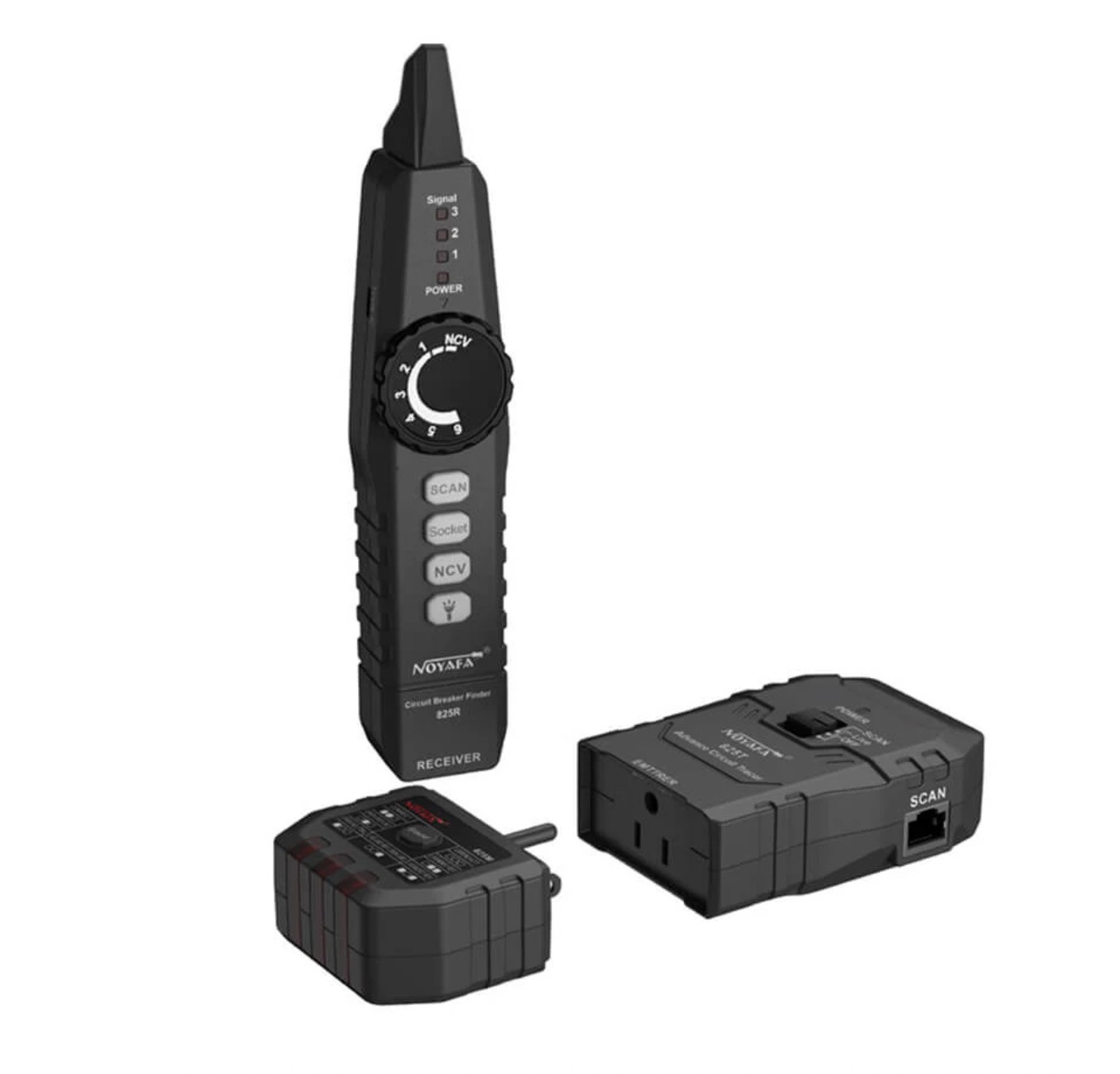
Features
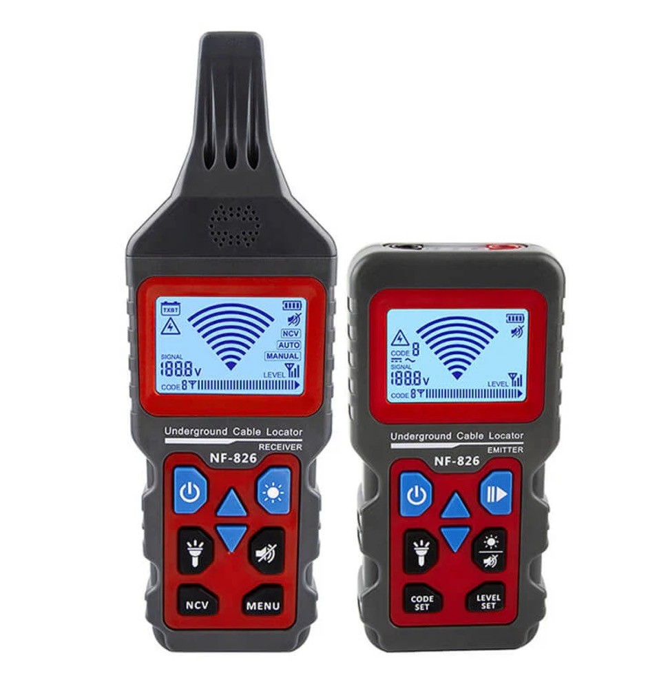
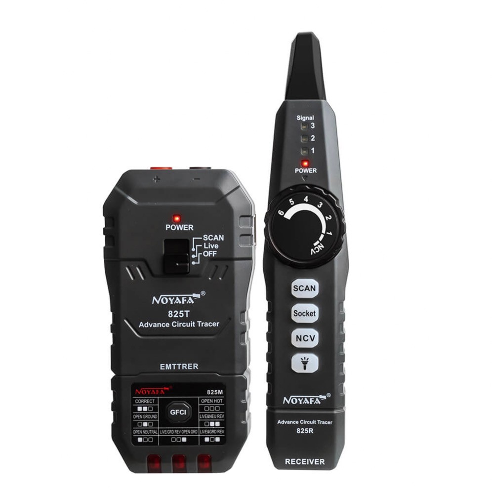
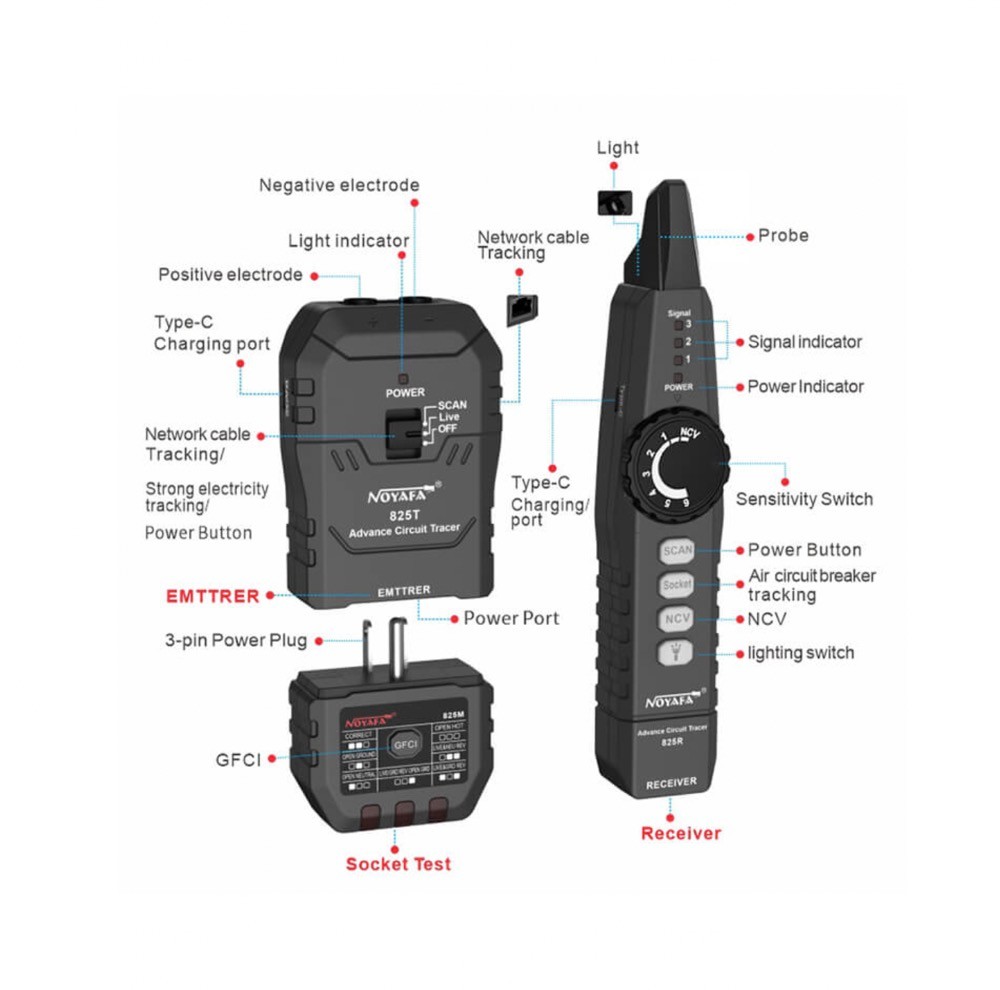
6-in-1 Electrical Kit: NF-825TMR is a multifunction electrical circuit tracing and testing kit. With 3 components and provided accessories, you can trace circuits or electric wires, locate circuit breakers, detect wiring faults, test outlets, find network cables, and detect voltage.
Circuit Tracer: Trace a live (energized) or open (de-energized) circuit, conduit or pipes, and a single wire in a bundle. The probe and tone generator will precisely indicate the wiring through a drywall, cement block, and underground.
Wire Fault Locator: NF-825TMR tells the location of short circuits in cables and wires without breaking the wall and ceiling.
Circuit Breaker Finder: Plug the Outlet Tester part into an outlet with the adapter and find the corresponding circuit breaker in the box with the toner probe.
GFCI Outlet Tester: Plug and detect the wiring status of an outlet without uncapping. Indicates the fault directly without manual checking, making re-wiring easy and fast.
RJ45 Network Cable Tracer: Track down the whereabouts of a network cable with a network toner.
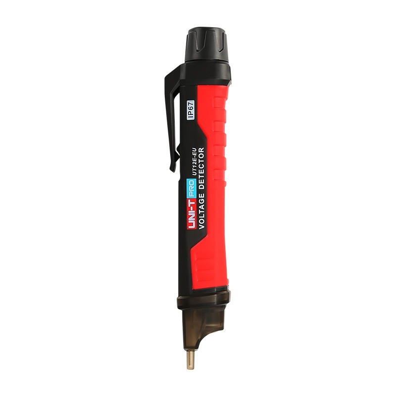
Contactless Voltage Detector: The probe of the Receiver part can serve as a voltage detector. Identify if an object carries electric flow before starting repair. Make working safe and sound.
Fair Price, Complete Package: We provide every accessory needed like alligator clips, adapter cables and plugs and a type-C charging cable. With all the necessary kits, this product is sold at an amicable price.
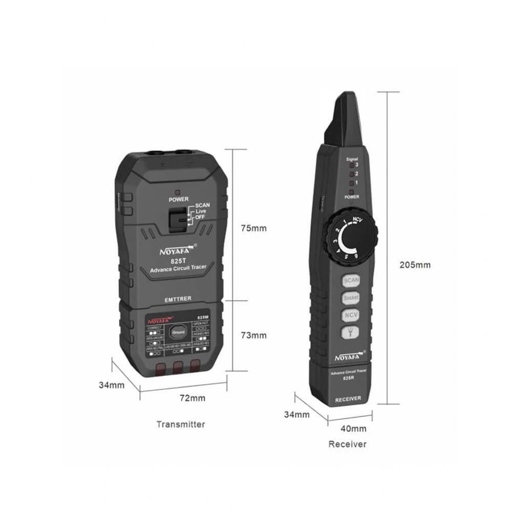
Technical parameters

Accessories