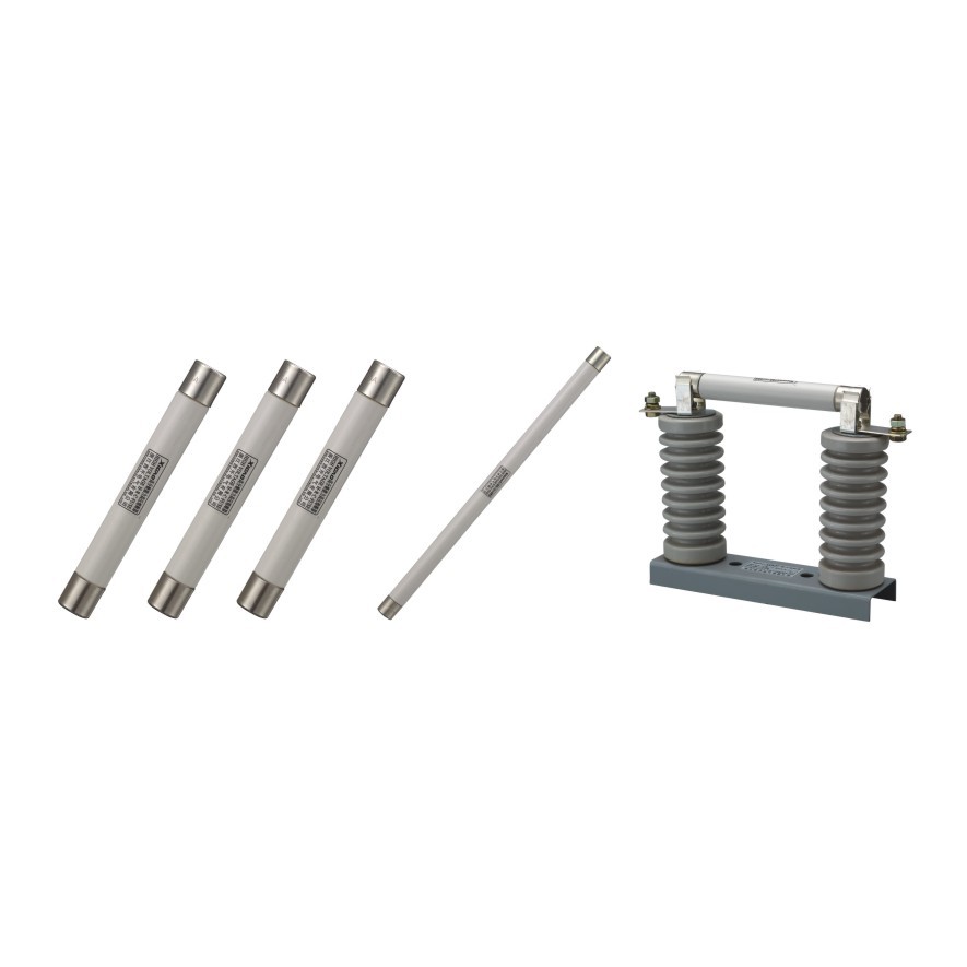
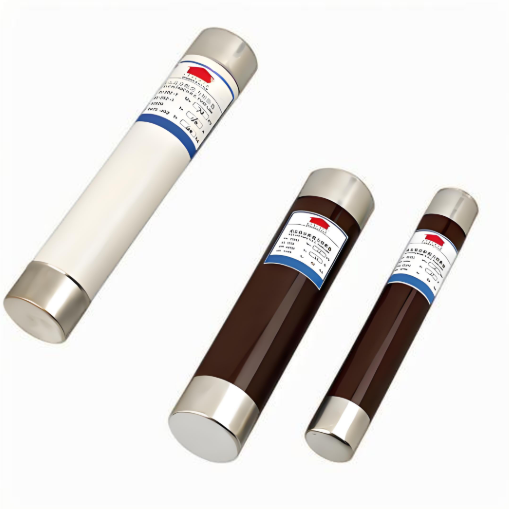
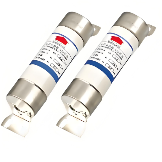
High Voltage Current-Limiting Fuse(For motor protection)
discuss personally
Model
| Brand | Wone |
| Model NO. | High Voltage Current-Limiting Fuse(For motor protection) |
| Rated voltage | 12kV |
| Rated normal current | 100A |
| Breaking capacity | 63kA |
| Series | Current-Limiting Fuse |
Characteristic brief :
Rated voltage from 3.6KV to 12KV.
Wide range of rated current from 31,5A to 400A.
BS type and DIN type are all available.
Powerful pyrotechnic or spnng striker.
H.R.C.
Current-limiting.
Low power dissipation, low temperature rise.
Operation extremely quickly, high reliability.
With motor circuit in senes.
Isolating & protecting motor.
Conforming to stanaards: GB15166.2 DIN43625 BS2692-1 IEC60282-1.
Model illustration:

Technical Parameters:

Fuse base table:

External&installation dimensions(Unit:tmm)

BS Type XRNM1 single fuse link

BS Type XRNM1 double fuse link

BS Type XRNM1 three fuse link

DIN Type XRNM2
How does a high-voltage current-limiting fuse (for motor protection) work?
Normal State:
During normal operation of the motor, the high-voltage current-limiting fuse has very low resistance, allowing the normal operating current to pass through without significantly affecting the motor circuit. It behaves like a well-conducting conductor.
When an overload or short-circuit fault occurs in the motor, causing the current to exceed the rated current of the fuse, the fusible element rapidly heats up due to the thermal effect of the current. Given the large magnitude of the fault current, the fusible element quickly reaches its melting point and melts, generating an arc.
At this point, the arc-quenching system, which includes materials such as quartz sand, absorbs the heat from the arc, causing it to extinguish rapidly. During this process, the fuse limits the peak value of the fault current, preventing the motor from experiencing excessive current surges.