| Brand | Wone |
| Model NO. | Fuse links for expulsion fuse cutout |
| Rated capacity of transformer | 200kVA |
| Full load current of transformer | 11.55A |
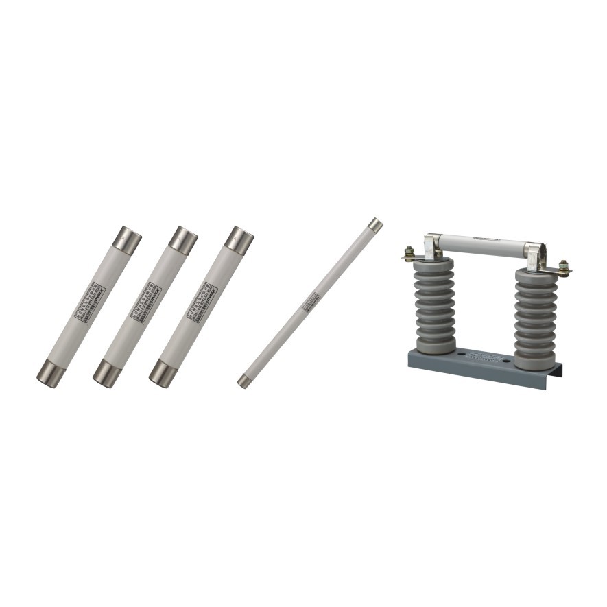
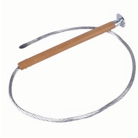
| Series | Fuse Links |
Characteristic brief :
Type K, type T, type H and type SLOW-FAST fuse link manufacture and test according to the latest international standard IEC 60282-2:2008 & IEEE Std C37.41-2008 & IEEE Std C37.42-2009.
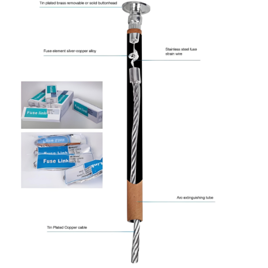
Fusible element adopts the material of silver-copper alloy.Using precision technology and strict testing to guarantee accurate characteristics of time-current.
Fusible element be crimping to fasten cable wire,and fixed by high strength strain wire.That guarantee excellent mechanical strength.it will not be affected,even if under external factors such as vibration and high current impact.
The Arc extinguishing tube has excellent performance of arc extinguishing when low current overload fault.
We also supply Type K and Type T twin pigtails fuse link, The twin pigtails fuse link is convenient and easier to install in the fuse cutout than conventional single pigtail fuse links. The twin pigtails attach under the attachment stud on each side separately.
Technical Parameters:
Type K Fuse Links:


11-15kv Fuse link length 21'(533mm)
24-27kv Fuse link length 23'(584mm)
33-38kv Fuse link length 31'(787mm)
Type T Fuse Links:


11-15kv Fuse link length 21'(533mm)
24-27kv Fuse link length 23'(584mm)
33-38kv Fuse link length 31'(787mm)
Type H Fuse Links:


11-15kv Fuse link length 21'(533mm)
24-27kv Fuse link length 23'(584mm)
33-38kv Fuse link length 31'(787mm)
Type Slofast Fuse Links:


11kv Fuse link leght 21'(533mm)
27kv Fuse link leght 23'(584mm)
33kv Fuse link leght 31'(787mm)
Type K Fuse Link Selection For Using Of Distribution Transformer Protection.The corresponding fuse is selected according to the time-current characteristics of the transformer,usually according to the rated current of the transformer.

NOTE: Rated capacity of transformer <160kVA,the rated current of the selected fuse links should be 2-3 times of the full load current of the transformer. Rated capacity of transformer >160kVA,the rated current of the selected fuse links should be 1.5-2 times of the full load current of the transformer.