• DS16 126kV 252kV 363kV 420kV 550kV High voltage disconnect switch
DS16 126kV 252kV 363kV 420kV 550kV High voltage disconnect switch
discuss personally
Model
DS16B-550/4000-63
DS16B-550/3150-50
DS16B-420/3150-50
DS16B-363/5000-63
DS16B-363/3150-50
DS16B-252/5000-63
DS16B-252/3150-50
DS16B-126/3150-40
DS16B-126/2500-40
Basic info
Brand ROCKWILL
Model NO. DS16 126kV 252kV 363kV 420kV 550kV High voltage disconnect switch
Rated voltage 550kV
Rated normal current 4000A
Series DS16
Product Detail

Description:

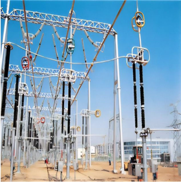
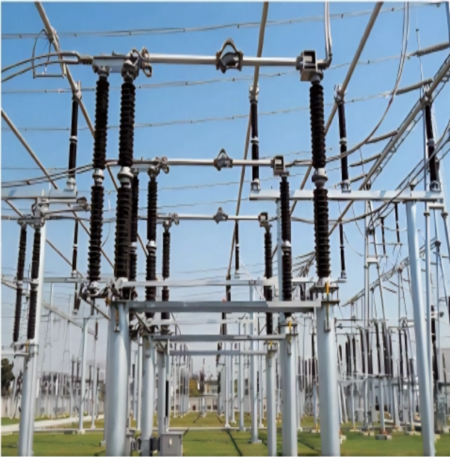
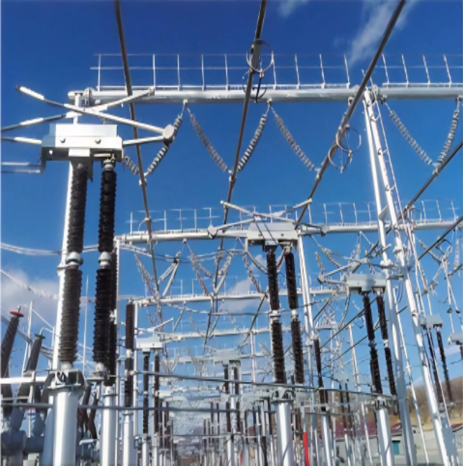
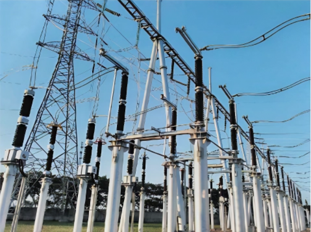
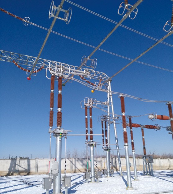
DS16 series disconnector adopts single-column single-arm vertical telescopic structure, which is mainly composed of base, insulator, conductive system, operating mechanism, etc. The disconnector is operated by CJ11 motor operating mechanism for opening and closing. The attached ground switch is mainly composed of ground switch system and operating mechanism, and each group of ground switches is operated by a CJ11 motor operating mechanism for opening and closing.


Main Features:


  •  Simple and compact structure, small footprint.

  • Strong product flow capacity, long mechanical life.

  • Optimized spring design, light and smooth operation.

  •  High seismic performance, can resist nine degrees of earthquake intensity.

  • The layout is flexible, convenient for users to choose.
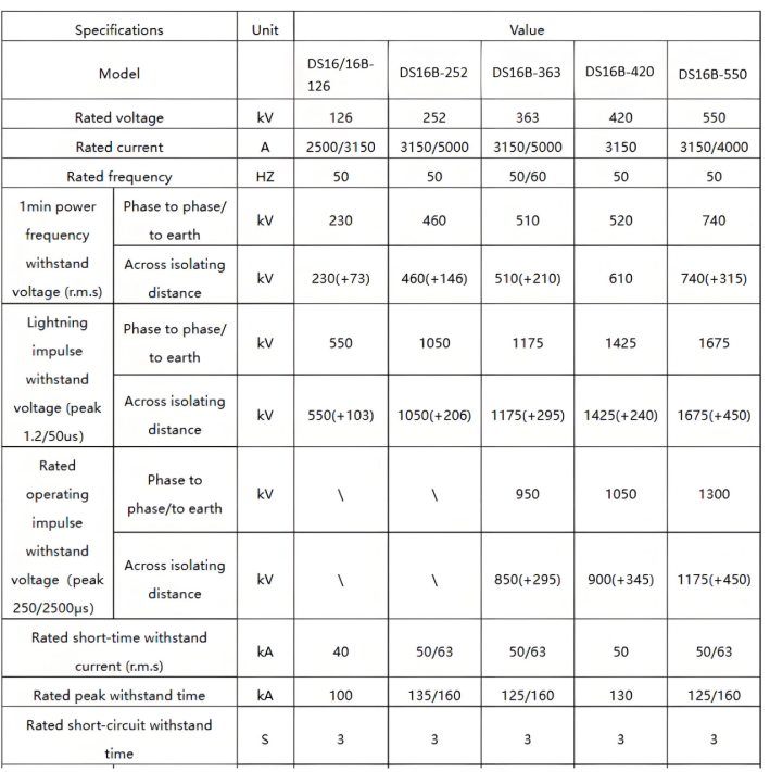
Technical parameter


image.png


What are the operation modes of the disconnector?

Operation Methods:

  • Manual: Manual isolator switches are simple to operate and cost-effective. They are suitable for applications where operations are infrequent, speed is not critical, and operators can easily access the site.

  • Electric: Electric isolator switches are ideal for large substations and environments that require a high degree of automation. They enable remote control and automated operations but come with higher costs and the need for a stable power supply and complex control systems.

  • Pneumatic: Pneumatic isolator switches offer rapid and powerful operation, making them suitable for applications requiring high-speed operation and explosion-proof environments (such as chemical plants and refineries). However, they require a compressed air system.

Operation Frequency:

If the isolator switch needs to be operated frequently, it is important to consider its mechanical life and the reliability of the operating mechanism. For example, in substations where frequent switching operations are required, it is advisable to select isolator switches with long mechanical life and reliable, flexible operating mechanisms to reduce maintenance costs and the incidence of failures.


Know your supplier
ROCKWILL
Rockwill Electric Group Global Manufacturer of High voltage and medium-voltage power equipment and smart grid solutions. Headquartered in Wenzhou, China. Serving 100+ countries with quality, innovation, and trust. What We Offer: • HV-MV switchgear (VCB, SF₆ circuit breakers, RMU, GIS) • Distribution transformers and substations • Smart grid and monitoring systems • Solar, wind, EV charging, and energy storage solutions • EPC turnkey power projects Certified: ISO 9001 / ISO 14001 / ISO 45001
Main Categories
High voltage
Business Type
Design/Manufacture/Sales
Highest Annual Export (USD)
$150,000,000
Professional Experience
16 years
Workplace
108000m²m²
占位
占位
Related Products
Related Knowledges
Failure Analysis and Design Optimization of Conventional Grounding Transformers
I. Core Cause of Damage: Electrodynamic Impact (Complying with GB/T 1094.5 / IEC 60076-5)The direct cause of high-voltage winding end collapse is the instantaneous electrodynamic impact induced by short-circuit current. When a single-phase grounding fault occurs in the system (such as lightning overvoltage, insulation breakdown, etc.), the grounding transformer, as the fault current path, withstands high-amplitude and steep-rise-rate short-circuit currents. According to Ampère's force law
Felix Spark
06/12/2025
Analysis of Grounding Transformer Operational Behavior Under System Single-Phase-to-Ground Fault Conditions
1 Theoretical AnalysisIn distribution networks, grounding transformers serve two key roles: powering low - voltage loads and connecting arc - suppression coils at neutrals for grounding protection. Grounding faults, the most common distribution network fault, heavily impact transformers’ operating characteristics, causing sharp changes in electromagnetic parameters and status.To study transformers’ dynamic behaviors under single - phase grounding faults, build this model: Assume a tr
Felix Spark
06/12/2025
Design Calculations for Neutral Grounding Schemes and Grounding Transformer Sizing in Utility-Scale Solar PV Plants
1 Classification of Neutral Grounding Methods for Solar Photovoltaic Power StationsInfluenced by differences in voltage levels and grid structures across regions, the neutral grounding methods of power systems are mainly categorized into non-effective grounding and effective grounding. Non-effective grounding includes neutral grounding via arc suppression coils and neutral ungrounded systems, while effective grounding comprises neutral solid grounding and neutral grounding via resistors. The sel
Dyson
06/12/2025
Zero-Sequence Impedance Characterization of Dry-Type Grounding Transformer with ZN Connection
In a neutral-insulated three-phase power system, an earthing transformer provides an artificial neutral point, which can be solidly earthed or earthed via reactors/arc suppression coils. The ZNyn11 connection is typical, where zero-sequence magnetomotive forces in the inner/outer half-windings of the same core column cancel out, balancing fault currents in series windings and minimizing zero-sequence leakage flux/impedance.Zero-sequence impedance is critical: it determines fault current magnitud
Dyson
06/12/2025
Case Analysis on Maloperation of Grounding Transformer Overcurrent Protection Relay
The neutral grounding mode refers to the connection between the power system neutral point and ground. In China's 35 kV and below systems, common methods include ungrounded neutral, arc-suppression coil grounding, and small-resistance grounding. The ungrounded mode is widely used as it allows short-term operation during single-phase grounding faults, while small-resistance grounding has become mainstream for its fast fault removal and overvoltage limitation. Many substations install grounding tr
Felix Spark
06/12/2025
Discussion on the Design of Low Zero-Sequence Impedance Grounding Transformers
With the expansion of power system scale and the cableization process of urban power grids, the capacitive current in 6kV/10kV/35kV power grids has significantly increased (generally exceeding 10A). As power grids at this voltage level mostly adopt neutral ungrounded operation mode, and the distribution voltage side of main transformers is usually in delta connection, lacking a natural grounding point, the arc during ground faults cannot be reliably extinguished, necessitating the introduction o
Dyson
06/11/2025
×
Inquiry
Download
Experts Electrical is dedicated to serving the personnel in the global power industry.
Join Experts Electrical, not only can you discover power equipment and power knowledge, but also canhnd like - minded friends!
商品视频播放