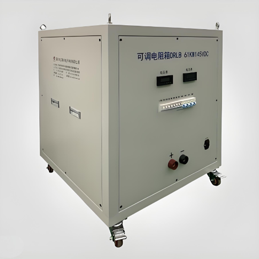
DC Load Bank- 61KW145VDC
discuss personally
Model
| Brand | Wone |
| Model NO. | DC Load Bank- 61KW145VDC |
| Rated voltage | DC145V |
| Power | 200KW |
| Series | LB |
Feature
It can reach the electrical parameters with high power (1kW to 10MW),high voltage ( AC 110V to 690V) or high current (10000A or more).
According to the needs to design the load steps,configure intelligent digital display meter,all protections can be configured optionally (Overheating alarm, Short circuit protection, Overheating protection, Fan overloading protection, Emergency stop button etc.).
In addition, our water-cooled load banks can also be equipped with cooling system and water tower.Customized solutions could be available upon request.
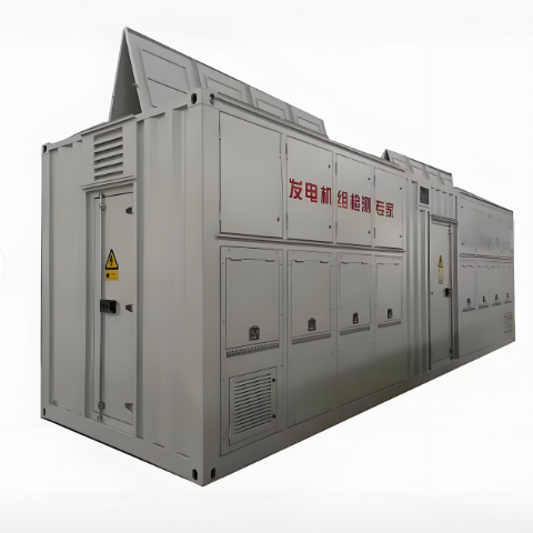
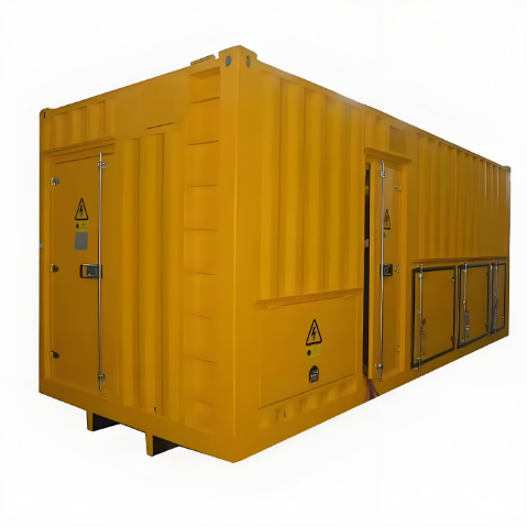
Load Bank Structure
When a single resistor can't meet load demand, multiple resistors are combined in series and parallel to increase power to meet the requirements.
The internal load resistors are circularly cooled by the axial fans.
The types of load built-in resistors are: high power wire wound resistors, aluminum housed resistors, high energy resistors, plate resistors, stainless steel resistors, high voltage resistors.
Notes
There shall be no flammable and explosive corrosive medium in the installation scope.
Connect the load and instrument power supply according to the identification on the equipment panel. After confirming that the voltage is normal, turn on the instrument power switch on the enclosure. At this time, all instruments display "0", all fans operate normally, and connect the load power supply .
To ensure safety, please do not touch the cabinet surface (except the panel) to prevent scalding.
After the load bank stops working, please delay 30 minutes to turn off the power supply of the fans, so as to avoid the accumulation of high temperature causing damage to other parts (such as instruments, switches, etc.)
There will be light smoke when the load is used for the first time,which is a normal phenomenon that silicone resin volatilizes when it meets high temperature medium.
Application Area
Generator test, power supply equipment, battery test, frequency converter, elevator, sub arc welding machine, lifting machinery, construction machinery, ship, rolling mill, wire drawing machine, centrifuge, UPS power supply, pulse load application, winch, generator, transformer, starting, braking, speed regulation and load test, as well as medical, railway, automobile, military and industrial control environment, etc.