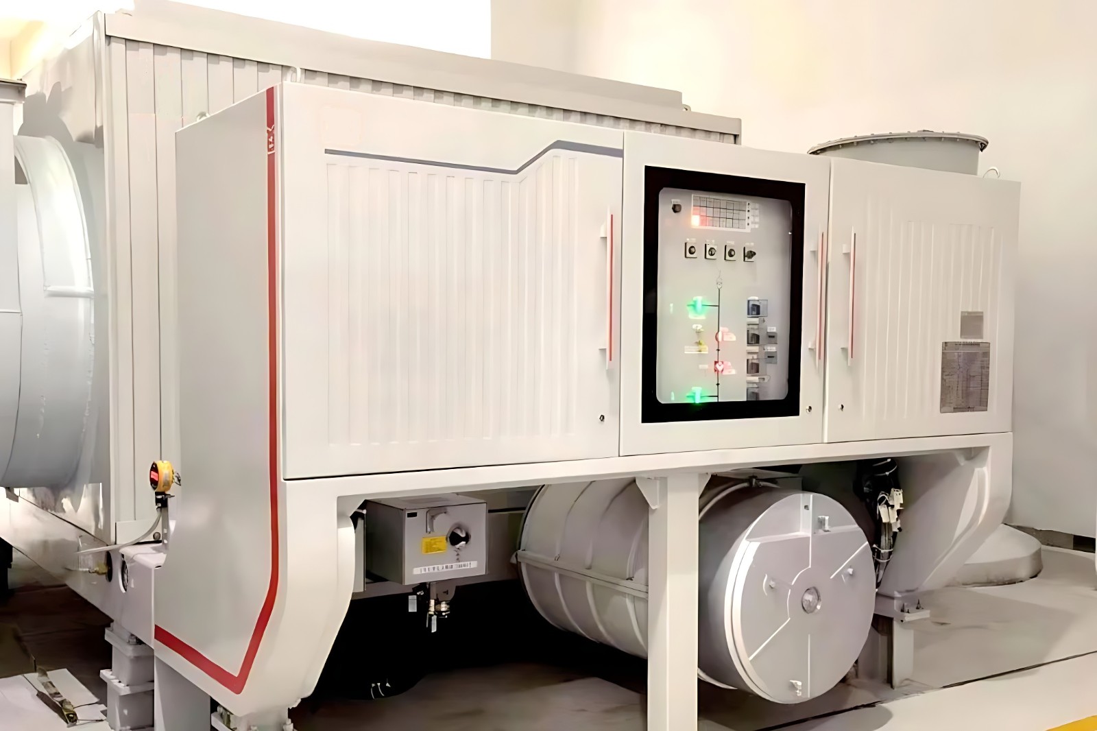
Complete Set of Electric Brake Switch for 120kA Hydro-turbine Generating Units
discuss personally
Model

| Brand | ROCKWILL |
| Model NO. | Complete Set of Electric Brake Switch for 120kA Hydro-turbine Generating Units |
| Rated voltage | 24kV |
| Rated normal current | 15000 |
| Series | Circuit Breaker |
Description:
This product is an essential switch equipment for achieving rapid shutdown of large hydroelectric generators. In 2019, it was appraised by the National Energy Administration and its comprehensive technical performance is at the leading domestic and international level. Currently, it has supplied 28 products to the Wudongde and Baihetan hydropower stations.
Product Performance:
High braking performance parameters: it has the capacity of braking current 30,000A and braking time 50 minutes.
High mechanical reliability: the brake switch and earthing switch can meet the mechanical life requirements of operation for 10,000 times.
Strong making capacity: the brake switch successfully passed the load current breaking and making test, and the current is 28,000A.
Reliable safety protection measures: pressure release device is installed at the top of the brake switch. When the gas pressure in the arc extinguishing chamber exceeds 1.2 MPa due to an accident, the gas will be released to ensure the safety of the personnel and surrounding equipment, The product design can ensure the stable operation of the power plant.
Product Structure:
Product consists of three single poles, and each pole has an individual enclosed metal enclosure mounted on the same chassis.
Brake switch is equipped with hydraulic spring operating mechanism; earthing switch is equipped with a motor operating mechanism; the driving modes are all three-phase mechanical linkage.
The main circuit adopts natural cooling.
Each operating mechanism is installed on the side of the product close to the control cabinet.
SF6 is used as insulation and arc-extinguishing medium for brake switch, The arc-striking contact adopts ablation-resistant copper-tungsten material, which effectively improves the reliability and electrical life of the brake switch.
The earthing switch takes air as insulation medium, the fixed contact is installed on the support of the main circuit, the moving side is installed on the bottom plate of the box body, and the moving contact is connected with the single phase enclosure and forms the earthing circuit through the closed bus bar connected with the moving contact.
The overall structure of brake switch is compact and convenient for installation and maintenance on site.
Typical applications:

Main technical parameters:

What is the standard for the opening time and opening time of the generator circuit breaker?
The opening and closing times for generator circuit breakers do not have a single fixed standard. The specific standards vary depending on the type of circuit breaker, voltage level, application scenario, and relevant standards and regulations. Below is a detailed introduction to the relevant standards:
Closing Time (Making Time):
Standard Range: Generally, the closing time for generator circuit breakers is typically between a few tens of milliseconds to over one hundred milliseconds. For example, common medium-voltage generator circuit breakers may have a closing time in the range of 30ms to 80ms, while high-voltage, high-capacity generator circuit breakers may have slightly longer closing times, but generally within 100ms.
Relevant Standards: According to relevant standards, the three-phase asynchronism closing time for generator circuit breakers should not exceed 5ms.
Opening Time (Breaking Time):
Standard Range: The opening time is the sum of the closing time and the arc burning time. The value can vary based on multiple factors. Generally, for medium-voltage generator circuit breakers, the opening time may be around 50ms to 150ms, while for high-voltage, high-capacity generator circuit breakers, the opening time may be around 100ms to 250ms.
Relevant Standards: For different voltage levels and types of generator circuit breakers, the transient recovery voltage during the interruption of short-circuit currents, load currents, and out-of-step currents should meet the corresponding standard requirements. The first-pole factor and magnitude factor can be taken as 1.5.