| Brand | RW Energy |
| Model NO. | Advanced Recloser Controller |
| Rated voltage | 230V ±20% |
| Rated frequency | 50/60Hz |
| Electric energy consumption | ≤5W |
| Version | V2.3.0-FA |
| Series | RWK-65 |
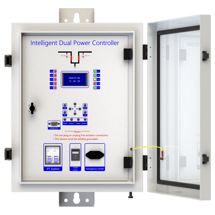
Description
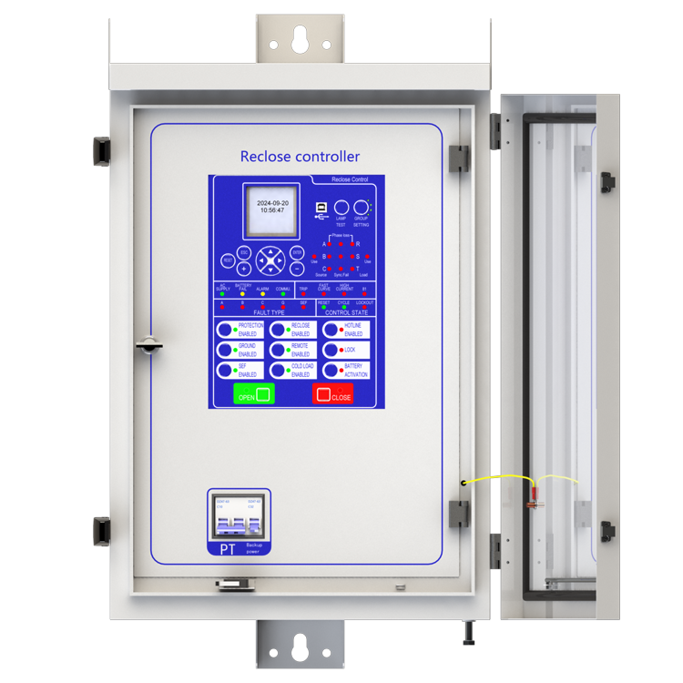
RWK-65 is an intelligent medium Voltage controller used in overhead line grid monitoring for the purpose of overhead line protection. It can be equipped with CW(VB) type vacuum circuit breaker to achieve automatic monitoring, fault analysis and store event records.
This unit offers safe line switching of faults on the power grid and provides automatic power recovery. RWK-65 series is suitable for up to 35kV outdoor switchgear include: vacuum circuit breakers, oil circuit breakers and gas circuit breakers. RWK-65 intelligent controller is equipped with line protection, control, measurement and monitoring of Voltage and current signals integrated automation and control devices outdoors.
RWK is a automatic management unit for single way/multi ways/ring network/two power sourcing, provided with all Voltage and current signals and all functions. RWK-65 column switch intelligent controller supports: Wireless (GSM/GPRS/CDMA), Ethernet mode, WIFI, optical fiber, power line carrier, RS232/485, RJ45 and other forms of communication, and can access other station premises equipment (such as TTU, FTU, DTU, etc.).
Main function introduction
1. Local Feeder Automation:
1) Adaptive comprehensive type, Adaptive comprehensive feeder automation is achieved through the "voltage loss opening, power delay closing" method, combined with short circuit/ground fault detection technology and fault path priority processing control strategy, in conjunction with the secondary closing of substation outgoing switches, to achieve fault localization and isolation adaptation of multi branch and multi connection distribution network structures. The first closing isolates the fault section, and the second closing restores power supply to no fault sections.
2) Voltage time type, The "voltage time type" feeder automation is achieved by combining the working characteristics of the switch "no voltage opening, power delay closing" with the secondary closing of the substation outgoing switch. The first closing isolates the fault section, and the secondary closing restores the power supply to the no fault section.
3) Voltage current time type, The voltage current time type adds discrimination for fault current and grounding current on the basis of the voltage time type, following the basic logic of closing within the X time limit of power on, detecting residual voltage lockout within the Y time limit, losing voltage within the Y time limit after closing, and detecting fault current lockout and opening. At the same time, it has the logic of locking and opening without detecting fault current within the Y time limit after closing, thereby accelerating the process of fault isolation. If the switch adopts a spring operated mechanism, it can be quickly isolated from instantaneous faults by adding a power loss delayed opening (in conjunction with the fast reclosing time of the substation outgoing switch).
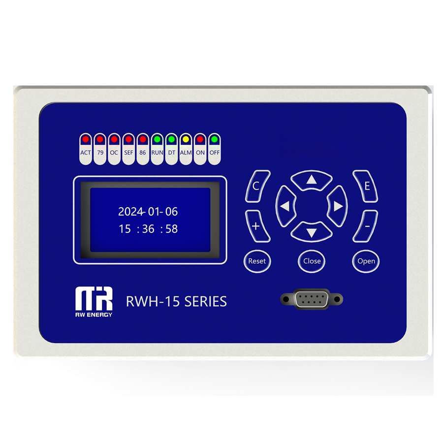
2. Protection relay functions:
1) 79 Auto Reclose (Reclose) ,
2) 50P Instantaneous/Definite-Time Overcurrent (P.OC) ,
3) 51P Phase Time-Overcurrent(P.Fast curve/P.Delay curve),
4) 50/67P Directional Phase Overcurrent (P.OC-Direction mode (2-Forward /3-Reverse)),
5) 51/67P Directional Phase Time-Overcurrent (P.Fast curve/P.Delay curve-Direction mode (2-Forward/3-Reverse)),
6) 50G/N Ground Instantaneous/Definite-Time Overcurrent (G.OC),
7) 51G/N Ground Time-Overcurrent (G.Fast curve/G.Delay curve),
8) 50/67G/N Directional Ground Overcurrent (G.OC- Direction mode (2-Forward/3-Reverse)) ,
9) 51/67G/P Directional Ground Time-Overcurrent (P.Fast curve/P.Delay curve-Direction mode (2-Forward/3-Reverse)),
10) 50SEF Sensitive Earth Fault (SEF),
11) 50/67G/N Directional Sensitive Earth Fault (SEF-Direction mode (2-Forward/ 3-Reverse)) ,
12) 59/27TN Earth Fault Protection With 3RD Harmonics (SEF-Harmonic inhibit enabled) ,
13) 51C Cold Load,
14) TRSOTF Switch-Onto-Fault (SOTF) ,
15) 81 Frequency protection ,
16) 46 Negative- Sequence Overcurrent (Nega.Seq.OC),
17) 27 Under Voltage (L.Under volt),
18) 59 Over Voltage (L.Over volt),
19) 59N Zero-Sequence Over Voltage (N.Over volt),
20) 25N Synchronism-Check,
21) 25/79 Synchronism-Check/Auto Reclose,
22) 60 Voltage unbalance,
23) 32 Power direction,
24) Inrush,
25) Loss of phase,
26) Live load block,
27) High gas,
28) High temperature,
29) hotline protection.
3. Supervision functions:
1) 74T/CCS Trip & Close Circuit Supervision,
2) 60VTS. VT Supervision.
4. Control functions:
1) 86 Lockout,
2) circuit-breaker control.
5. Monitoring Functions:
1) Primary/Secondary Phases and Earth Currents,
2) Phases Current with 2nd Harmonics and Earth Current With 3RD Harmonics,
3) Direction, Primary/Secondary Line and Phase Voltages,
4) Apparent Power and Power Factor,
5) Real and Reactive Power,
6) Energy and History Energy,
7) Max Demand and Month Max Demand,
8) Positive Phase Sequence Voltage,
9) Negative Phase Sequence Voltage & Current,
10) Zero Phase Sequence Voltage,
11) Frequency, Binary Input/Output status,
12) Trip circuit healthy/failure,
13) Time and date,
14) Trip, alarm,
15) signal records, Counters,
16) Wear, Outage.
6. Communication functions:
a. Communication interface: RS485X1,RJ45X1
b. Communication protocol: IEC60870-5-101; IEC60870-5-104; DNP3.0; Modbus-RTU
c. PC software: RWK381HB-V2.1.3,The address of the information body can be edited and queried by PC software,
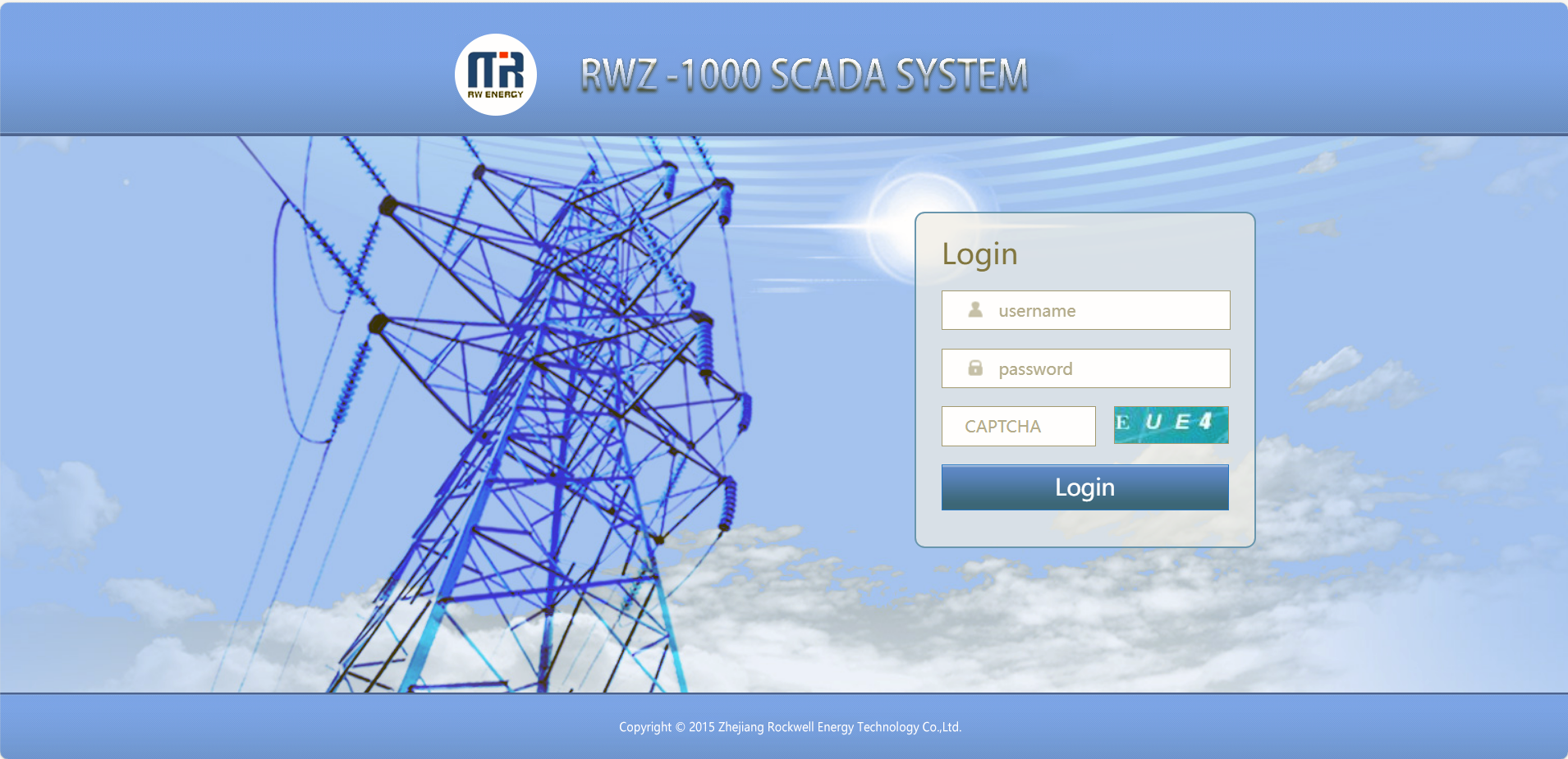
d. SCADA system: SCADA systems that support the four protocols shown in "b.”.
7. Data Storage functions:
1) Event Records,
2) Fault Records,
3) Measurands.
8. remote signaling remote measuring, remote controlling function can be customized address.
Technology parameters

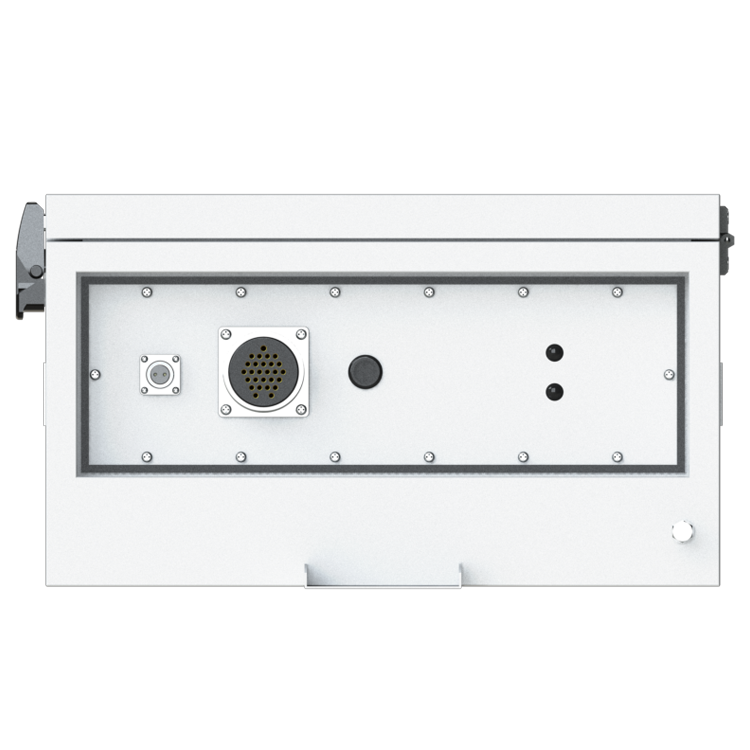
Device structure


About customization
The following optional functions are available: Power supply rated at 110V/60Hz,Two three-phase voltage sensors, cabinet heating defrosting device, battery upgrade to lithium battery or other storage equipment, GPRS communication module,1~2 signal indicators,1~4 protection pressure plates, the second voltage transformer, custom aviation socket signal definition.
For detailed customization, please contact the salesman.
Q: What is a recloser?
A: The reclosing device is a device that can automatically detect the fault current, and automatically cut off the circuit when the fault occurs, and then perform multiple reclosing operations.
Q: What is the function of the recloser?
A: It is mainly used in the distribution network. When there is a temporary fault in the line (such as a branch touching the line for a short time), the reclosing device restores power supply by reclosing operation, which greatly reduces the outage time and scope and improves power supply reliability.
Q: How does the recloser determine the type of failure?
A: It monitors characteristics such as the magnitude and duration of fault currents. If the fault is permanent, after a preset number of reclosing, the reclosing device will be locked to avoid further damage to the device.
Q: What are the application scenarios of reclosers?
A: It is widely used in the urban distribution network and rural power supply network, which can effectively cope with various possible line failures and ensure the stable supply of power.