| Brand | ROCKWILL |
| Model NO. | ZF28-420 TYPE SF6 GAS INSULATED SWITCHGEAR |
| Rated voltage | 420kV |
| Rated normal current | 4000A |
| Series | ZF28 |
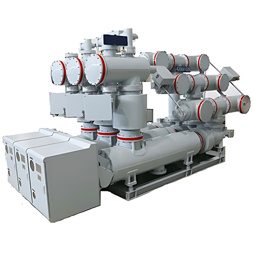
Product overview:
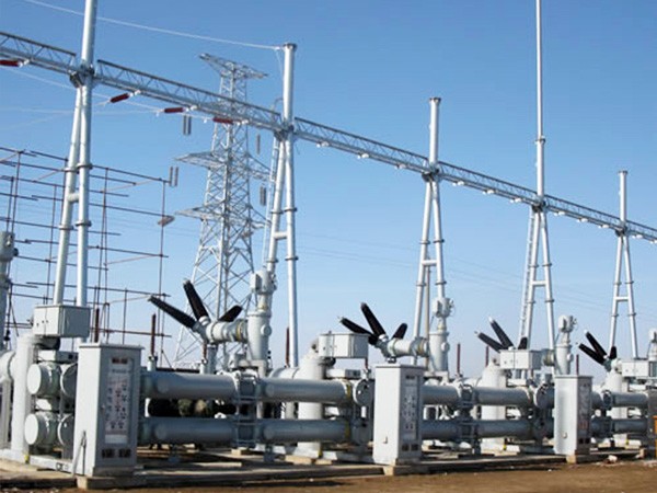
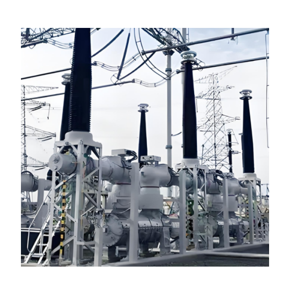
ZF28-420 type GIS is composed of standard modules through flanged joint, which can meet the demand for substation optimization design through the flexible combination between modules. It saves space and conforms to technical requests.
This product can be applied to power system, power generation, rail transportation, petrochemical, metallurgy, mining, building materials and other large industrial consumer.
Features and advantages of the product:
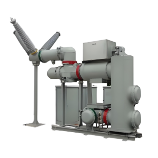
Horizontal circuit breaker structure, integrated transportation, high space utilization.
Fusion of high parameters and high reliabilityCircuit breaker, disconnector and grounding switch have a mechanical life of 10,000 times.
Advanced circuit breaker, excellent breaking capacity.
Mature pure spring operating mechanism application.
Basin insulator with aluminum flange with double seal structure.
Import of key components, accessories and major production equipment.
The GIS phase spacing is 670mm and the standard spacing width is 2050mm (see layout). The whole interval of three-phase integrated transportation, its technological innovation level is domestic leading, international advanced level.
Arrangement of circuit breaker is horizontal, it’s convenient for overhauling and emergency maintenance; it also will make lighter impact to the ground.
Excellent insulation level and low partial discharge. The only company in the industry that can achieve: under 1.2 times phase voltage (1.2×420/√3 = 291kV), the partial discharge of intervals is lower than 5pC, the partial discharge of the insulator is lower than 3pC.
Technical Parameters:

What is a GIS device?
GIS is the English abbreviation of Gas Insulated Switchgear, which is generally translated as gas-insulated fully enclosed combined electrical appliances, usually using SF6 gas as the insulating medium, including circuit breaker (CB), disconnector (DS), earthing switch (ES, FES), bus (BUS), current transformer (CT), voltage transformer (VT), lightning arrester (LA) and other high-voltage components. At present, GIS equipment products have covered the voltage level range of 72.5 kV ~ 1200 kV.