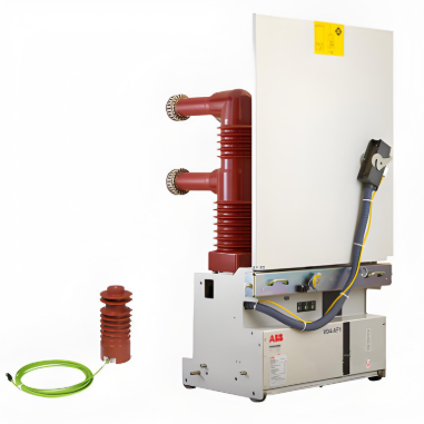
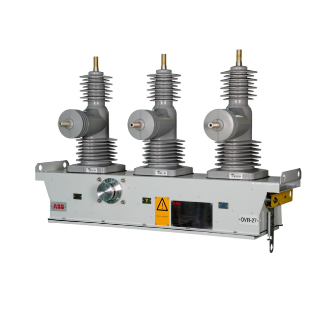
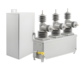
36/38kV Indoor vacuum circuit breaker with servomotor actuation and controlled switching
discuss personally
Model

| Brand | ABB |
| Model NO. | 36/38kV Indoor vacuum circuit breaker with servomotor actuation and controlled switching |
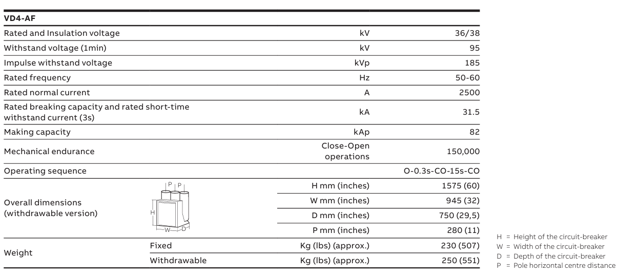
| Rated voltage | 38kV |
| Rated normal current | 2500A |
| Rated frequency | 50/60Hz |
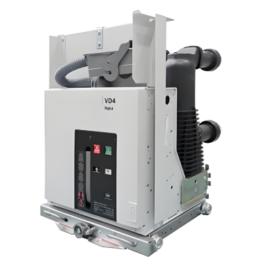
| Series | VD4-AF1 |
Description:
ABB offers its new vacuum circuit breaker with servomotor actuation and controlled switching technology up to 38kV, 2500A, 31.5kA and up to 150,000 operations with extremely low inrush, to support your business needs for diverse installations like steel industries applications.
Feature:
Protect your assets
• Enables increased lifespan of transformers by more than 10% in e.g. 3 years
• Reduction of hazards due to improved protection range
• Up to 5-to-10-times higher endurance performance than the market standard
Maximize your output
• Reduced total cost due to elimination of downtime for breaker overhaul and a lifespan 5 times the market standard, with predictive health indication
• Reduced compensation losses up to 10% while increasing power quality
• Fast and reliable support thanks to ABB’s global footprint
Optimize your investment
Elimination of inrush limiting reactors and resistances, leading to significant cost and space savings
Cost saving by as much as 20%, using same ratings, same interfaces of existing MV substation thanks to optimized footprint equivalent to standard distribution breakers
Technical Characteristics:
Type tested according to IEC 62271-100
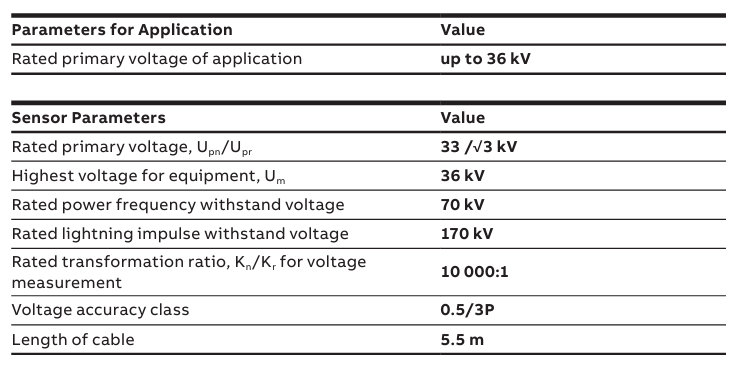
Technical Characteristics of sensor :
Type tested according to IEC 60044-7