| Brand | Vziman |
| Model NO. | 3 Phase AC Power Voltage Stabilizer 50KVA 100KVA 200KVA 500KVA 2000KVA 380V 415V Automatic Adjustment Voltage Regulator |
| Rated capacity | 60KVA |
| Series | SWB-S |
Description:
SBW-S、DBW-S series intelligent numerical control (microcomputer type) compensated AC power regulators are based on the perfect combination of traditional high-power compensated voltage regulators and modern intelligent control technology, allowing users to enjoy the reliability and convenience of parameter setting and maintenance brought by modern advanced control circuits, highlighting the safety, stability Energy saving and humanization of man-machine interface. The regulated power supply can be equipped with a variety of intelligent interfaces to realize the functions of "remote signaling, telemetry and remote control".
Features:
Delay output function (add output contactor).
Lightning protection device: it can provide good surge protection in case of instantaneous change of power grid and induced lightning stroke.
EMI filtering device: it can effectively filter the harmonic interference of power grid.
Phase sequence and phase loss protection function.
RS485 interface: realize remote control, remote signaling and telemetry function.
It can be widely used in industrial and mining enterprises, scientific research, posts and telecommunications, military, railway, transportation, hospitals, elevators, bowling equipment, air conditioners, hotels and other places with high requirements for power grid power supply.The normal operating conditions of sbw-s and dbw-s series intelligent control (single chip microcomputer control) complementary AC power regulators are:
temperature:-15°C - 40°C.
Altitude:less than 1000m.
Relative humidity:<90%.
The relative humidity installation site shall be free of gas, steam, chemical deposition, dust, dirt and other explosive and corrosive media that seriously affect the insulation strength of regulated power supply.
The installation site shall be free from serious vibration and turbulence.
Any special use conditions that do not meet the above provisions shall be determined through consultation with the user and our factory.
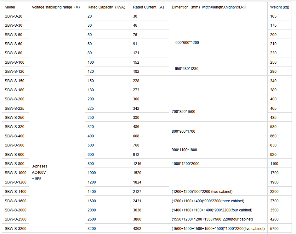
Parameters:

Wiring diagram:
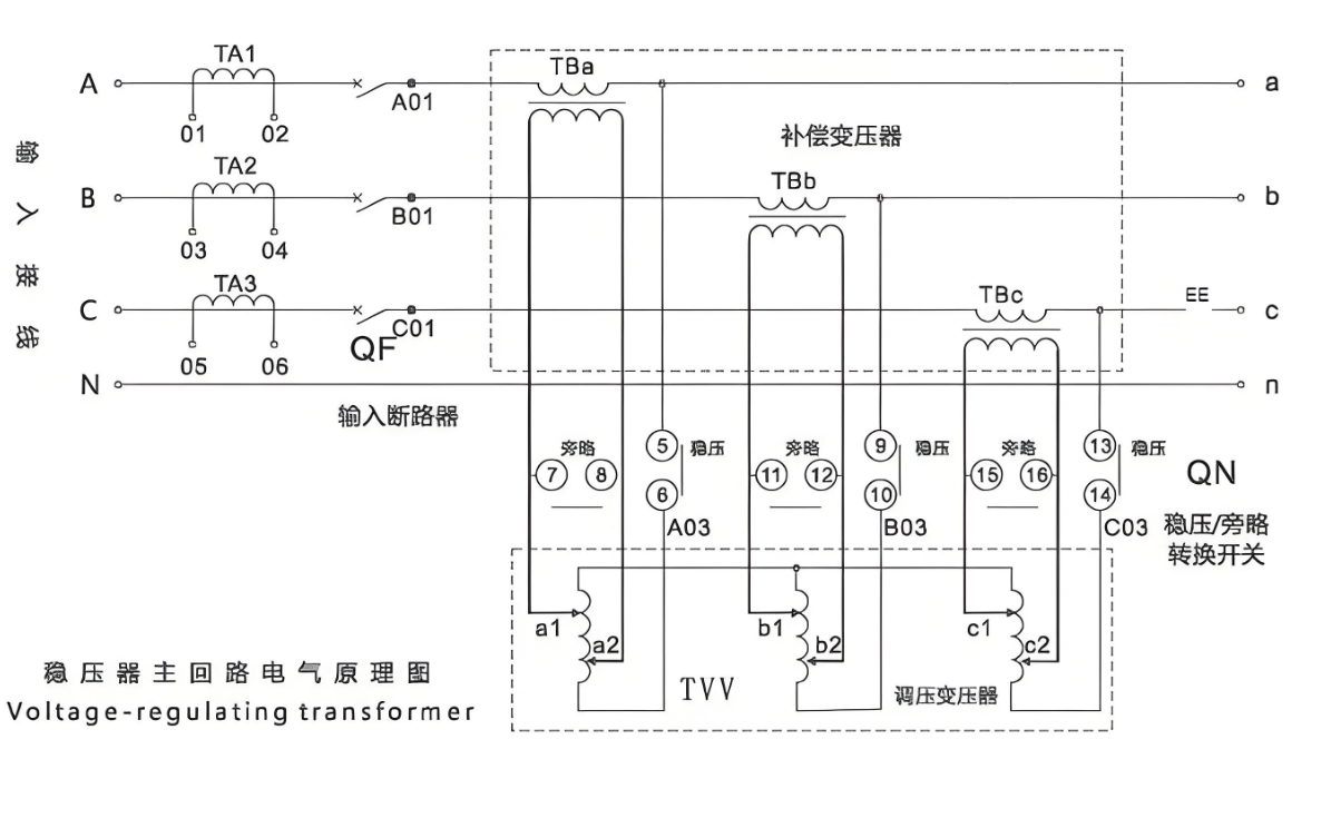
SBW-S、DBW-S series intelligent numerical control (single chip microcomputer control) compensation AC power regulator is mainly composed of input circuit breaker QF, three-phase voltage regulating transformer TB, three-phase voltage regulating transformer TVV, servo motor control and transmission mechanism, voltage stabilizing / bypass transfer switch and protection circuit. The electrical principle of the main circuit is shown in the figure below.
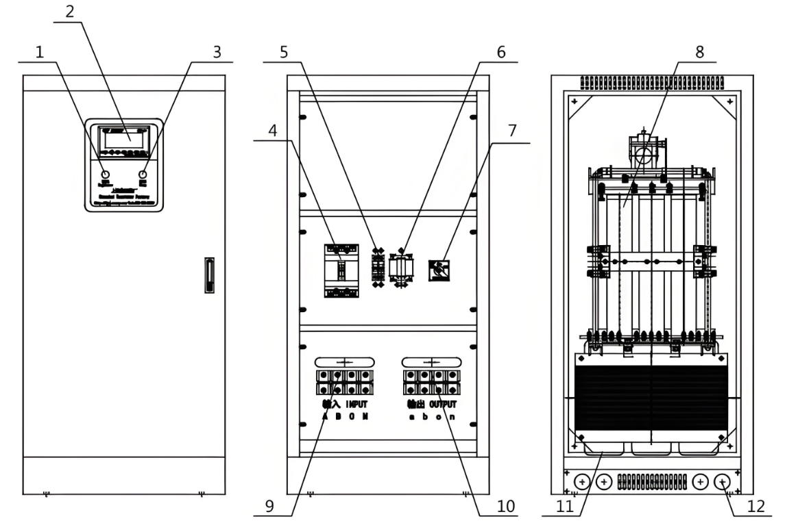
Voltage stabilizing indicator.
Intelligent control display.
Stop button.
Main power switch.
Control circuit fuse.
Control power transformer.
Mains / voltage stabilizing transfer switch.
Voltage regulating transformer (auxiliary transformer).
Input terminal block.
Output terminal block.
Compensation transformer (main transformer).
Inlet and outlet holes (knock off holes).
What is the co-operation principle of the three-phase AC power regulator?
Working Principle:
The working principle of a three-phase AC voltage stabilizer mainly includes the following steps:
Input Voltage Detection: The voltage stabilizer first detects the input three-phase AC voltage.
Voltage Comparison: The detected input voltage is compared with the preset target voltage.
Adjusting Circuit: Based on the result of the voltage comparison, the voltage stabilizer adjusts the output voltage through the adjusting circuit. Common adjustment methods include:
Voltage-Regulating Transformer: Adjusting the voltage by changing the turns ratio of the transformer.
Servo Motor Drive: Driving the carbon brush to move on the sliding rheostat by the servo motor to change the resistance value and thus adjust the voltage.
Electronic Control: Using electronic components (such as thyristors, IGBTs, etc.) to adjust the voltage.
Output Voltage Stabilization: The adjusted voltage is supplied to the load through the output port to ensure that the output voltage remains stable within the predetermined range.
