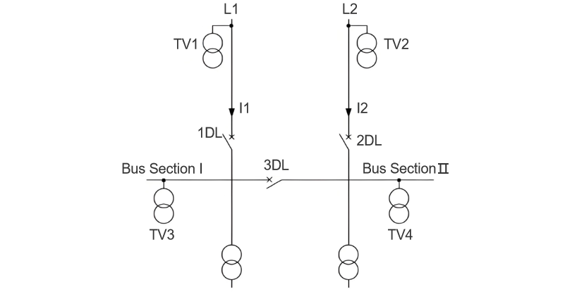
Impact Analysis of Voltage Transformer Installation on Line Side vs. Load Side of Power Inlet Circuit Breaker for (ATS)

James
07/03/2025

Automatic backup switching (ABTS) devices are core components ensuring the safe, reliable, and stable operation of factory power grids. Their startup logic strictly follows the dual criteria of "loss of voltage in the working power supply + no - current detection", effectively avoiding misjudgments caused by secondary disconnection of voltage transformers (VTs) or maloperations of ABTS due to secondary circuit faults of current transformers (CTs). The activation condition requires both "no voltage and no current" or "voltage/current values below the protection setting", with no exceptions.
ABTS relies on VTs to collect voltage signals and CTs to collect current signals. Thus, the installation positions of these transformers directly determine the accuracy of the device in judging the status of the working power supply. Among them, regardless of whether CTs are installed on the upper or lower side of the power inlet circuit breaker, ABTS can accurately identify "circuit breaker current - carrying status and busbar load - carrying conditions"; however, there are significant differences in how ABTS judges the live status of busbars when VTs are installed on the upper side (inlet side) versus the lower side (busbar side) of the circuit breaker, which requires focused analysis. The system wiring is shown in Figure 1.
1. Voltage Transformer Installed on the Upper Side of the Power Inlet Circuit Breaker (Inlet VT)
(1) Normal Operation of the Inlet Power Supply
When ABTS takes power from the line voltage transformer TV1, if circuit breaker 1DL is in the "working position + closed state", TV1 collects the inlet voltage, which is equivalent to the busbar voltage. ABTS then determines that Section I busbar is live.
(2) Loss of Inlet Power Supply
When the inlet power supply fails, TV1 collects a voltage of zero and the CT collects a current of zero, triggering ABTS to act: first trip 1DL, then close bus - tie circuit breaker 3DL, restoring power to Section I busbar and allowing the load to continue operating.
(3) Maloperation of the Circuit Breaker (Core Hidden Risk Scenario)
If 1DL switches from the closed to the open position due to misoperation or mechanical failure, Section I busbar loses power and the load shuts down. The CT collects a current of zero, but TV1 still collects the normal inlet - side voltage (not dropping to the protection setting), so ABTS fails to detect "busbar voltage loss" and cannot start. 3DL cannot close, causing prolonged power loss on Section I busbar and severe production interruptions.
(4) Logic Optimization Solution
Precise identification requires implementing a "circuit breaker position interlock + voltage criterion": TV1 - collected voltage is equivalent to the busbar voltage only when 1DL is in the "working position + closed state"; if the circuit breaker position is abnormal (non - working position/open state), ABTS forcibly judges the busbar voltage as 0. Additionally, a "circuit breaker position verification" logic must be added: after detecting busbar voltage loss, ABTS verifies the status of 1DL before deciding to "trip 1DL + close 3DL" or directly "close 3DL".
2. Voltage Transformer Installed on the Lower Side of the Power Inlet Circuit Breaker (Busbar VT)
When ABTS takes power from the busbar voltage transformer TV3, if circuit breaker 1DL is in the "working position + closed state", TV3 directly collects the voltage of Section I busbar, and ABTS obtains the actual busbar voltage signal.
(1) Loss of Inlet Power Supply
When the inlet power supply fails or 1DL maloperates to the open position, TV3 collects a voltage of zero and the CT collects a current of zero, triggering ABTS to act:
  • If the inlet power supply fails: trip 1DL → close 3DL to restore busbar power;
  • If the circuit breaker maloperates: directly close 3DL to restore busbar power, with no load interruption.
(2) Advantage Analysis
The busbar VT can "realtime and directly reflect the busbar live status" without relying on circuit breaker position criteria. ABTS has a simpler action logic, accurately identifying busbar voltage loss scenarios and avoiding misoperation/non - operation risks.
3. Comparative Analysis of the Two Installation Schemes
(1) Complexity of Action Logic
  • Inlet - side installation (TV1): Requires adding "circuit breaker position verification + voltage conversion logic", increasing the difficulty of ABTS action judgment;
  • Busbar - side installation (TV3): Directly collects busbar voltage with clear logic and high action reliability.
(2) Potential Risks (Major Hidden Danger of Inlet - Side Installation)
If TV1 on the inlet side is paralleled with line L1, when L1 loses power, ABTS triggers the "trip 1DL → close 3DL" action. The busbar voltage is then reverse - fed to L1 through TV1, causing a "voltage reverse charging accident": at best, tripping the air circuit breaker on the L1 side and causing secondary voltage loss; at worst, damaging equipment and even triggering personal electric shock risks.
4. Conclusion and Recommendations
To ensure ABTS "acts accurately and reliably" during busbar voltage loss and avoid voltage reverse charging accidents when VTs are paralleled, VTs should be installed on the lower side (busbar side) of the power inlet circuit breaker to directly collect busbar voltage via the busbar VT. This enables realtime reflection of the actual busbar status, providing reliable criteria for ABTS. It ensures the device acts quickly and accurately during busbar voltage loss, minimizing impacts on production and daily life.
James

Professionalism builds strength. As an expert in the installation and operation of electrical equipment, I am proficient in the installation process and strictly adhere to standards. I skillfully master the operation essentials and can swiftly eliminate faults. With a heart that constantly explores new knowledge, I illuminate the path to the efficient operation of electrical equipment.

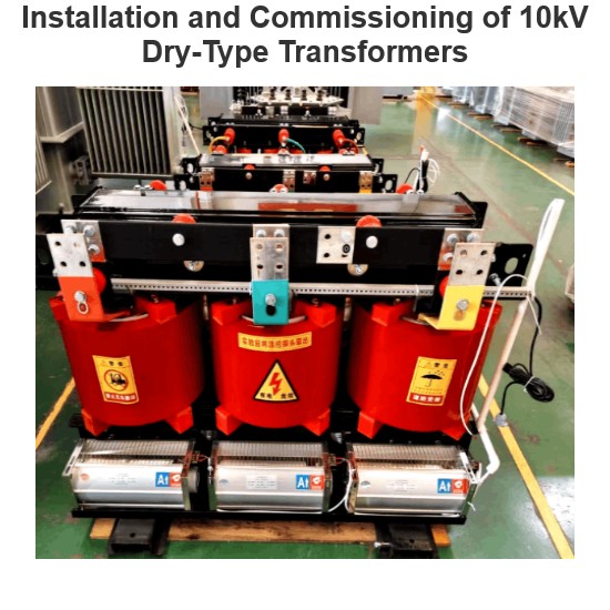
Installation and Commissioning of 10kV Dry-Type Transformers
By James, 10 Years of Electrical Equipment Maintenance ExperienceHi everyone, I’m James, and I’ve been working in electrical equipment fault repair for 10 years.Over the past decade, I’ve worked in factories, substations, and distribution rooms of all sizes, involved in the installation, commissioning, maintenance, and troubleshooting of dry-type transformers. Dry-type transformers are among the most common electrical devices we deal with on a daily basis.Today, a new colleague
James
07/01/2025
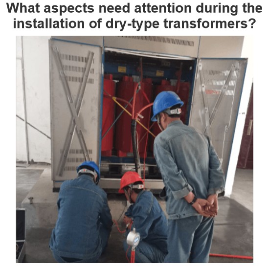
What aspects need attention during the installation of dry-type transformers?
1 Pre - installation PreparationAs a front - line installer, I know very well that the preparation work before installing a dry - type transformer must be thorough. First, I will carefully review the design drawings and technical documents, and check one by one the technical parameters such as the model specification, rated capacity, and voltage level of the transformer to ensure they are in full compliance with the design requirements. Then, I will conduct an unpacking inspection of the transfo
James
07/01/2025
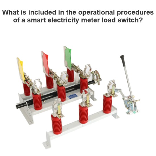
What is included in the operational procedures of a smart electricity meter load switch?
As a frontline operator who deals with smart electricity meters daily, I’m well - versed in the design and operational norms of load switches (both internal and external) in these meters. Below, I’ll break down the technical requirements and practical key points based on my on - site experience for easy reference.I. Basic Understanding of Internal and External Load SwitchesIn the type specifications for single - phase and three - phase smart electricity meters (such as environmental
James
06/28/2025
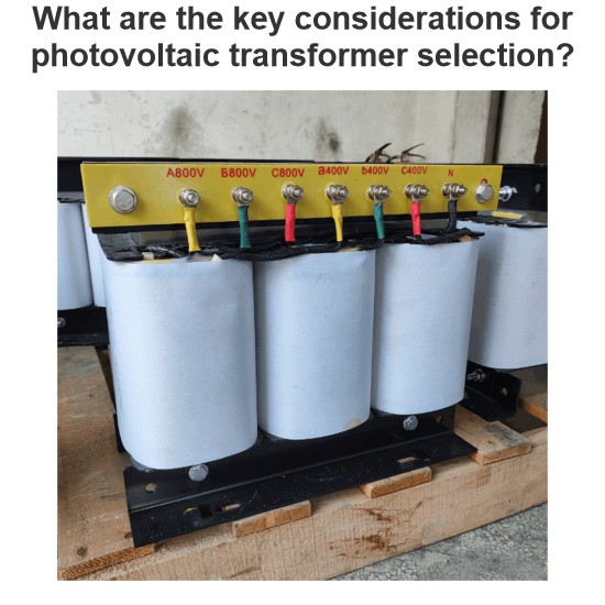
What are the key considerations for photovoltaic transformer selection?
Sizing Principles and Technical Parameters of Photovoltaic TransformersSizing photovoltaic transformers requires a comprehensive consideration of multiple factors, includingcapacity matching, voltage ratio selection, short - circuit impedance setting, insulation class determination, and thermal design optimization. The key sizing principles are as follows:(I) Capacity Matching: Fundamental for Load BearingCapacity matching is thecore prerequisitein sizing photovoltaic transformers. It requires a
Echo
06/27/2025
Inquiry
Download
Experts Electrical is dedicated to serving the personnel in the global power industry.
Join Experts Electrical, not only can you discover power equipment and power knowledge, but also canhnd like - minded friends!