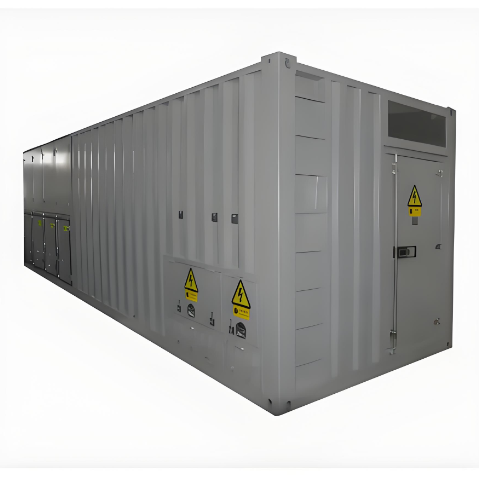
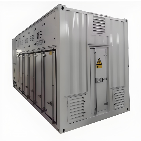
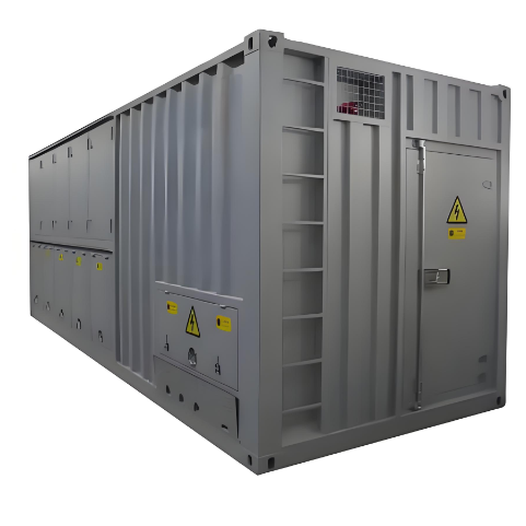
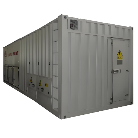
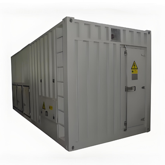
2MW High Voltage Dummy Load for Generator
discuss personally
Model
| Brand | Wone |
| Model NO. | 2MW High Voltage Dummy Load for Generator |
| Rated voltage | 400V |
| Power | 2000KW |
| Series | LB |
Description
The machine has its own cooling system, when temperature of the machine is too high that it unload automatically. The equipment used to test the output power and loading capacity of High Voltage Generator. The load bank power input adopts sectional type, with remote control, easy to operation.Load bank using energy consumption method, air forced cooling, air dispersion, so that machine noise reduces greatly.
Parameter


System Constitution

Test function
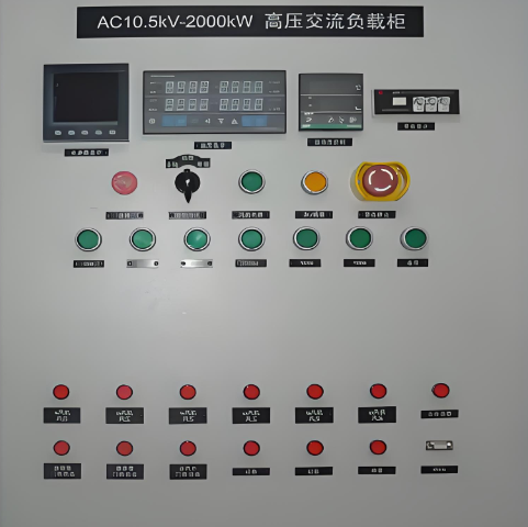
Load bank testing: User could load any power within rated power, can test stable state three-phase voltage, current, active power, reactive power, apparent power, power factor, frequency, running time of generating set.
Control Mode: local, remote or intelligent control(software) for choosing.
Local Control: local control panel with several power steps, load or unload by switch on-off and read parameter values from measuring meter.
Remote Control:through the switch in the remote control box, control the load over a long distance.
Intelligent Control: through data processing software, realize all the test functions, display, record and manage the testing data, and generate curves, graphs and tables can be printed.
Control Mode Interlock: with control mode switch, no matter chooses which mode, operation of other mode is invalid, avoid the clash.
One-key load/unload: Whether load/unload by local control panel or by PC software control, user can pre-set the user can pre-set the power then press the master load button..
Software function
Communication Mode: using photoelectric isolated RS485 communication serial port connect to PC, and with great anti-interference performance to make system control stable. Through converts like USB or RS232 realize communication protocol conversion.
Load Mode: manual load or automatic load
Manual Load: input power and power factor, and load according to the preset value.
Automatic Load: set several load stages and duration, then complete the process according this stages automatically. 0%- 25%,- 50%,- 75%, -100%
Real-time Monitor: through software display main parameter value, such as voltage, current, power, power factor, frequency and time.
Security monitoring and control: monitor working state of the load bank by watching software light, when abnormally stop and protect, it can show the reason.
Data Collection Interval: the minimum data resolving time is 2s.