• 1kW / 1.036 KWh portable power station
  • 1kW / 1.036 KWh portable power station
1kW / 1.036 KWh portable power station
discuss personally
Model
WN-1000
Basic info
Brand Wone
Model NO. 1kW / 1.036 kWh portable power station
输出功率 1000W
Energy capacity 1036Wh
Series Portable power station
Product Detail

Description:

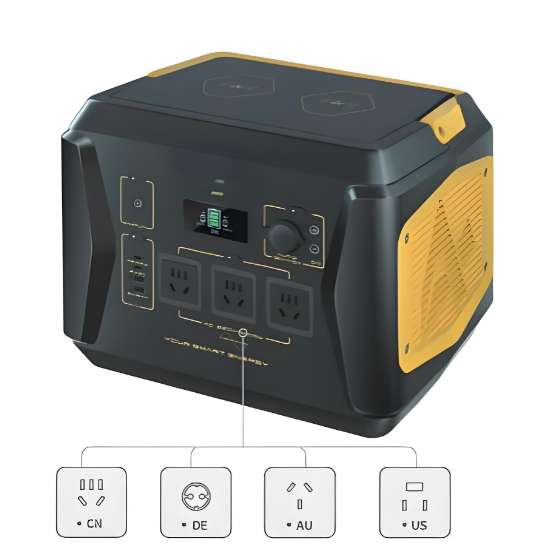
This 1kW / 1.036 kWh portable power station can support up to 12 devices simultaneously, is easy to carry (11kg), and ideal for outdoor activities as well as emergency power supply for homes. This is a lifestyle change-maker and the dream device for adventurers.

Feature:

  • 3- Level Brightness.

  • SOS Function.

  • Equipped with 2 Wireless Charging Pads.

  • Capable to Charge 12 Devices Simultaneously.

  • Big Capacity in Small Box.

Basic parameters:

image.png

Electrical Parameters:

image.png

How are portable charging stations overcharged protected?

Voltage Detection:

  • Function: The Battery Management System (BMS) continuously monitors the voltage of each battery cell.

  • Principle: When the voltage of a battery cell reaches or approaches the preset upper limit (for example, the upper limit of a lithium-ion battery is usually 4.2V), the BMS will trigger overcharge protection.

Current Detection:

  • Function: The BMS monitors the charging current.

  • Principle: If the charging current exceeds the preset safety threshold, the BMS will reduce the charging current or completely cut off the charging circuit.

Temperature Detection:

  • Function: The BMS monitors the temperature of the battery.

  • Principle: If the battery temperature exceeds the preset safety threshold (for example, 60°C), the BMS will reduce the charging current or completely cut off the charging circuit to prevent dangers caused by overheating.

Logic Control:

  • Function: The BMS makes logical judgments based on the data of voltage, current, and temperature to decide whether to activate overcharge protection.

  • Principle: The microprocessor built into the BMS will judge whether the battery is in an overcharged state according to the preset algorithms and thresholds. If overcharge conditions are detected, the BMS will execute corresponding protection measures.

Protection Measures:

  • Cutting off the Charging Circuit: The BMS cuts off the charging circuit by controlling the charging relay or MOSFET (Metal Oxide Semiconductor Field Effect Transistor) to prevent the current from continuing to flow into the battery.Reducing the Charging Current: In some cases, the BMS may first reduce the charging current to observe the changes in the battery state. If the battery voltage still rises, then the charging circuit will be completely cut off.

  • Alarm Notification: The BMS can issue an alarm through the display screen or indicator light to remind the user that the battery has reached a full charge state and the charger needs to be disconnected.


Know your supplier
Wone
Main Categories
High voltage/Low voltage/Wire cable/Instrument meters/New energy/Tester/Production equipment/Generator/Electrical fittings/Integrated Electrical Equipment
Business Type
Design/Manufacture/Sales
Highest Annual Export (USD)
$50,000,000
Professional Experience
1 years
Workplace
65666m²m²
占位
占位
Related Products
Related Knowledges
The design of the three-purpose grounding transformer
Underground Power Cable Transmission LinesDirect - buried power cable lines have large ground - distributed capacitance, causing high single - phase - to - ground short - circuit capacitive current. For 10 kV lines, if this current exceeds 10 A, arcs hardly self - extinguish, risking arc overvoltage and endangering line equipment. Arc extinction is thus necessary. With a Dyn - connected main transformer, an arc - suppression coil on the secondary neutral point suffices. For Yd - connected ones,
Dyson
06/12/2025
Failure Analysis and Design Optimization of Conventional Grounding Transformers
I. Core Cause of Damage: Electrodynamic Impact (Complying with GB/T 1094.5 / IEC 60076-5)The direct cause of high-voltage winding end collapse is the instantaneous electrodynamic impact induced by short-circuit current. When a single-phase grounding fault occurs in the system (such as lightning overvoltage, insulation breakdown, etc.), the grounding transformer, as the fault current path, withstands high-amplitude and steep-rise-rate short-circuit currents. According to Ampère's force law
Felix Spark
06/12/2025
Analysis of Grounding Transformer Operational Behavior Under System Single-Phase-to-Ground Fault Conditions
1 Theoretical AnalysisIn distribution networks, grounding transformers serve two key roles: powering low - voltage loads and connecting arc - suppression coils at neutrals for grounding protection. Grounding faults, the most common distribution network fault, heavily impact transformers’ operating characteristics, causing sharp changes in electromagnetic parameters and status.To study transformers’ dynamic behaviors under single - phase grounding faults, build this model: Assume a tr
Felix Spark
06/12/2025
Design Calculations for Neutral Grounding Schemes and Grounding Transformer Sizing in Utility-Scale Solar PV Plants
1 Classification of Neutral Grounding Methods for Solar Photovoltaic Power StationsInfluenced by differences in voltage levels and grid structures across regions, the neutral grounding methods of power systems are mainly categorized into non-effective grounding and effective grounding. Non-effective grounding includes neutral grounding via arc suppression coils and neutral ungrounded systems, while effective grounding comprises neutral solid grounding and neutral grounding via resistors. The sel
Dyson
06/12/2025
Zero-Sequence Impedance Characterization of Dry-Type Grounding Transformer with ZN Connection
In a neutral-insulated three-phase power system, an earthing transformer provides an artificial neutral point, which can be solidly earthed or earthed via reactors/arc suppression coils. The ZNyn11 connection is typical, where zero-sequence magnetomotive forces in the inner/outer half-windings of the same core column cancel out, balancing fault currents in series windings and minimizing zero-sequence leakage flux/impedance.Zero-sequence impedance is critical: it determines fault current magnitud
Dyson
06/12/2025
Case Analysis on Maloperation of Grounding Transformer Overcurrent Protection Relay
The neutral grounding mode refers to the connection between the power system neutral point and ground. In China's 35 kV and below systems, common methods include ungrounded neutral, arc-suppression coil grounding, and small-resistance grounding. The ungrounded mode is widely used as it allows short-term operation during single-phase grounding faults, while small-resistance grounding has become mainstream for its fast fault removal and overvoltage limitation. Many substations install grounding tr
Felix Spark
06/12/2025
×
Inquiry
Download
Experts Electrical is dedicated to serving the personnel in the global power industry.
Join Experts Electrical, not only can you discover power equipment and power knowledge, but also canhnd like - minded friends!
商品视频播放