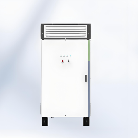
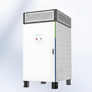
• 1725 KVA 2000KVA Power Conversion System (Central PCS)
  • 1725 KVA 2000KVA Power Conversion System (Central PCS)
  • 1725 KVA 2000KVA Power Conversion System (Central PCS)
1725 KVA 2000KVA Power Conversion System (Central PCS)
discuss personally
Model
WN-1725/2000-HA-UD
Basic info
Brand Wone
Model NO. 1725 KVA Power Conversion System (Central PCS)
Max.Efficiency 99%
AC output power 1725kVA
Max. DC voltage 1500V
Max. DC current 1936A
Max. AC output current 1046A
Series Power Conversion System
Product Detail

Features

  •  Max. efficiency up to 99%.

  • Full reactive power four-quadrant capability.

  •  IP65 protection degree.

  • Black start ability.

  • Support VSG function.

  • Millisecond-level Power response to EMS/SCADA.

  • Three level topology.

  •  Use alone or in combination with MV station.

DC Parameters:

image.png

AC parameters (On-Grid):

image.png

AC parameters (Off-Grid):

image.png

General data:

image.png

How the energy storage converter is short-circuit protected?

Current Detection

  • Function: Monitor the input and output currents of the converter in real time.

  • Principle: Use current sensors (such as Hall effect sensors, shunts, etc.) to detect the current. When a sudden increase in the current is detected and it exceeds the preset threshold, the system will determine that a short circuit may have occurred.

Overcurrent Protection

  • Function: Quickly cut off the power supply when an overcurrent is detected to prevent the short circuit from developing further.

  • Principle:Hardware Protection: Use hardware devices such as fast fuses, circuit breakers, or MOSFETs (Metal Oxide Semiconductor Field Effect Transistors) to cut off the current.

  • Software Protection: Execute the protection logic through a microprocessor or controller to control relays or MOSFETs to cut off the current.

Protection Measures

  • Cutting off the Power Supply: Cut off the power supply through relays or MOSFETs to prevent the short-circuit current from continuing to flow.

  • Alarm Notification: Issue an alarm through the display screen or indicator lights to remind the user that there is a short-circuit fault in the system.

  • Fault Isolation: When a short circuit is detected, isolate the faulty part to prevent the fault from spreading to other parts.

Know your supplier
Wone
Main Categories
High voltage/Low voltage/Wire cable/Instrument meters/New energy/Tester/Production equipment/Generator/Electrical fittings/Integrated Electrical Equipment
Business Type
Design/Manufacture/Sales
Highest Annual Export (USD)
$50,000,000
Professional Experience
1 years
Workplace
65666m²m²
占位
占位
Related Products
Related Knowledges
Failure Analysis and Design Optimization of Conventional Grounding Transformers
I. Core Cause of Damage: Electrodynamic Impact (Complying with GB/T 1094.5 / IEC 60076-5)The direct cause of high-voltage winding end collapse is the instantaneous electrodynamic impact induced by short-circuit current. When a single-phase grounding fault occurs in the system (such as lightning overvoltage, insulation breakdown, etc.), the grounding transformer, as the fault current path, withstands high-amplitude and steep-rise-rate short-circuit currents. According to Ampère's force law
Felix Spark
06/12/2025
Analysis of Grounding Transformer Operational Behavior Under System Single-Phase-to-Ground Fault Conditions
1 Theoretical AnalysisIn distribution networks, grounding transformers serve two key roles: powering low - voltage loads and connecting arc - suppression coils at neutrals for grounding protection. Grounding faults, the most common distribution network fault, heavily impact transformers’ operating characteristics, causing sharp changes in electromagnetic parameters and status.To study transformers’ dynamic behaviors under single - phase grounding faults, build this model: Assume a tr
Felix Spark
06/12/2025
Design Calculations for Neutral Grounding Schemes and Grounding Transformer Sizing in Utility-Scale Solar PV Plants
1 Classification of Neutral Grounding Methods for Solar Photovoltaic Power StationsInfluenced by differences in voltage levels and grid structures across regions, the neutral grounding methods of power systems are mainly categorized into non-effective grounding and effective grounding. Non-effective grounding includes neutral grounding via arc suppression coils and neutral ungrounded systems, while effective grounding comprises neutral solid grounding and neutral grounding via resistors. The sel
Dyson
06/12/2025
Zero-Sequence Impedance Characterization of Dry-Type Grounding Transformer with ZN Connection
In a neutral-insulated three-phase power system, an earthing transformer provides an artificial neutral point, which can be solidly earthed or earthed via reactors/arc suppression coils. The ZNyn11 connection is typical, where zero-sequence magnetomotive forces in the inner/outer half-windings of the same core column cancel out, balancing fault currents in series windings and minimizing zero-sequence leakage flux/impedance.Zero-sequence impedance is critical: it determines fault current magnitud
Dyson
06/12/2025
Case Analysis on Maloperation of Grounding Transformer Overcurrent Protection Relay
The neutral grounding mode refers to the connection between the power system neutral point and ground. In China's 35 kV and below systems, common methods include ungrounded neutral, arc-suppression coil grounding, and small-resistance grounding. The ungrounded mode is widely used as it allows short-term operation during single-phase grounding faults, while small-resistance grounding has become mainstream for its fast fault removal and overvoltage limitation. Many substations install grounding tr
Felix Spark
06/12/2025
Discussion on the Design of Low Zero-Sequence Impedance Grounding Transformers
With the expansion of power system scale and the cableization process of urban power grids, the capacitive current in 6kV/10kV/35kV power grids has significantly increased (generally exceeding 10A). As power grids at this voltage level mostly adopt neutral ungrounded operation mode, and the distribution voltage side of main transformers is usually in delta connection, lacking a natural grounding point, the arc during ground faults cannot be reliably extinguished, necessitating the introduction o
Dyson
06/11/2025
×
Inquiry
Download
Experts Electrical is dedicated to serving the personnel in the global power industry.
Join Experts Electrical, not only can you discover power equipment and power knowledge, but also canhnd like - minded friends!
商品视频播放